


A H 5 0 0 H a r d w a r e a n d
Operation Manual
6 - 2
6.1
Quick Start
T
he chapter provides a simple example, and leads users to create a traditional ladder diagram in ISPSoft in a
short time. However, in order to help users who are not familiar with IEC 61131-3 understand the functions
provided by ISPSoft,
and create a traditional ladder diagram, programming concepts related to IEC 61131-3
are not introduced in this chapter. F
or example, POUs, function blocks, variables, and etc. are not introduced.
6.1.1
Example
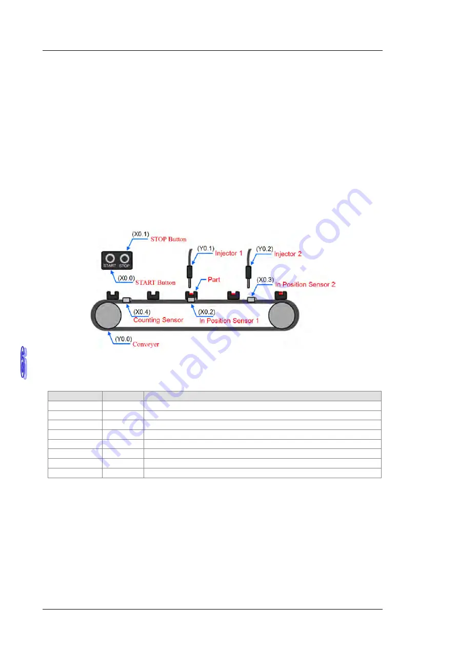
When the equipment operates,
the parts on the conveyer are conveyed from left to right
. If a sensor senses
that a part is under an injector, the PLC will send a trigger signal to the injector, and the injector will injects the
glue. How long the part will
be injected is set externally, and is not controlled by the pro
gram in the PLC.
H
owever, the program in the PLC must be able to turn the
trigger
signal OFF so that the
trigger
signal can be
sent next time.
There are two injectors above the conveyer, and the two injectors inject glue in the same way.
Besides, there is
a sensor at the left side of the conveyer.
When a part passes the sensor, the sensor value
increases by one increment.
If the sensor value is 100, the internal completion flag
will be
set to
ON. T
he state
of the flag can be used by other procedures later.
However, the use of the state of the flag is not introduced in
this example.
6.1.2
Hardware
In this example, the AH500 series CPU module used is
AHCPU530-EN
, the digital I/O module used is
AH16AP11R-5A
, and the main backplane used is
AHBP04M1-5A
.
The table below is an I/O allocation table.
Type
ID
Description
Digital input
X0.0
START button
Digital input
X0.1
STOP button
Digital input
X0.2
In position sensor 1
Digital input
X0.3
In position sensor 2
Digital input
X0.4
Counting sensor
Digital output
Y0.0
C
onveyer
Digital output
Y0.1
Trigger signal for injector 1
Digital output
Y0.2
Trigger signal for injector 2
6.1.3
Program
(1) W
hen the START button (X0.0) is turned from OFF to ON, the internal operation flag is set to ON, and the
conveyer (Y0.0) starts to run.
W
hen the STOP button (X0.1) is turned from OFF to ON, an error occurs
(the error flag is ON), the operation flag is reset to OFF, and the conveyer stops running.
(2) W
hen in position sensor 1 (X0.2) is ON, the trigger signal for injector 1 (Y0.1) is set to ON.
When in
position sensor 1 is OFF, the trigger signal for injector 1 is reset to OFF.
(3) W
hen in position sensor 2 (X0.3) is ON, the trigger signal for injector 2 (Y0.2) is set to ON.
When in
position sensor 2 is OFF, the trigger signal for injector 2 is reset
to OFF.
(4) W
hen the counting sensor (X0.4) is turned from OFF to ON, the sensor value increases by one
increment. I
f the sensor value is larger than or equal to 100, the internal completion flag will be set to ON.
Summary of Contents for AH500 series
Page 35: ...AH500 Hardware and Operation Manual 2 2 2 12 2 Profiles 2 117 2 12 3 Dimensions 2 118 ...
Page 153: ...AH500 Hardware and Operation Manual 2 120 MEMO ...
Page 167: ...AH500 Hardware and Operation Manual 3 14 MEMO ...
Page 343: ...AH500 Hardware and Operation Manual 6 38 MEMO ...
Page 361: ...AH500 Hardware and Operation Manual 7 18 MEMO ...
Page 403: ...Chapter 8 Hardware Configuration 8 42 MEMO ...
Page 412: ...Chapter 9 Network Configuration 9 9 ...
Page 445: ...AH500 Hardware and Operation Manual 9 42 MEMO ...
Page 552: ...Chapter 12 Troubleshooting 12 3 12 1 3 Troubleshooting Procedure ...
Page 649: ...AH500 Hardware and Operation Manual A 8 ...
Page 657: ...AH500 Hardware and Operation Manual A 16 MEMO ...
Page 658: ...B 1 Appendix B Device Addresses Table of Contents B 1 Device Addresses B 2 ...
Page 663: ...AH500 Hardware and Operation Manual C 4 MEMO ...
Page 681: ...AH500 Hardware and Operation Manual 3 14 MEMO ...


