


A H 5 0 0 H a r d w a r e a n d O p e r a t i o n M a n u a l
11 - 6
11.1.2.3
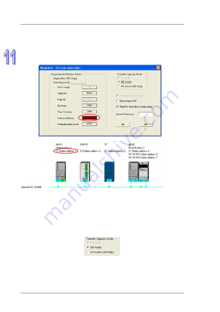
Setting Communication Parameters (Step 2)
After the system leads users to the second step, the users have to set the communication parameters in the
PLC Link Table Editor
window. The parameters uploaded through the master station are displayed at the left
part of the window. The setting of the communication parameters of all the slave stations in the same network
must be the same as the setting of the communication parameters of the master station. If no parameters are
uploaded, “Unknown” will be shown in the boxes at the left part of the window. If the station address uploaded is
different form the station address assigned o the master station, the
Station Address
box will become red.
Transfer Capacity Mode
The users can set 16 data exchange groups or 32 data exchange groups, depending on the model
selected. The users can select a maximum data length in the
Transfer Capacity Mode
section. Besides,
the maximum data length which can be set varies with the PLC which is designated as a master station.
Please refer to manuals for more information.
If an AH500 series CPU module or an AH500 series module is designated as a master station, the
450
words (AH Only)
option button in the
Transfer Capacity Mode
section can be selected. Only AH500
series CPU modules allow 450-word data to be exchanged. As a result, if the
450 words (AH Only)
option
button in the
Transfer Capacity Mode
section is selected, the DVP series PLCs and the other devices can
not execute a PLC Link.
Hold the RS485 Setting
Generally speaking, the communication parameters in a DVP series PLC will be restored to the default
values if the DVP series PLC is turned on after a power failure. However, if the
Hold the RS485 Setting
checkbox is selected, the communication parameters stored will be loaded again if a DVP series PLC runs
after it is stopped. Please refer to manuals for more information about the communication parameters in
DVP series PLCs.
Summary of Contents for AH500 series
Page 35: ...AH500 Hardware and Operation Manual 2 2 2 12 2 Profiles 2 117 2 12 3 Dimensions 2 118 ...
Page 153: ...AH500 Hardware and Operation Manual 2 120 MEMO ...
Page 167: ...AH500 Hardware and Operation Manual 3 14 MEMO ...
Page 343: ...AH500 Hardware and Operation Manual 6 38 MEMO ...
Page 361: ...AH500 Hardware and Operation Manual 7 18 MEMO ...
Page 403: ...Chapter 8 Hardware Configuration 8 42 MEMO ...
Page 412: ...Chapter 9 Network Configuration 9 9 ...
Page 445: ...AH500 Hardware and Operation Manual 9 42 MEMO ...
Page 552: ...Chapter 12 Troubleshooting 12 3 12 1 3 Troubleshooting Procedure ...
Page 649: ...AH500 Hardware and Operation Manual A 8 ...
Page 657: ...AH500 Hardware and Operation Manual A 16 MEMO ...
Page 658: ...B 1 Appendix B Device Addresses Table of Contents B 1 Device Addresses B 2 ...
Page 663: ...AH500 Hardware and Operation Manual C 4 MEMO ...
Page 681: ...AH500 Hardware and Operation Manual 3 14 MEMO ...


