Section 3: Operation
3-40
User’s Manual
Note that the two menus differ only in their user interface, so use whichever menu
best suits your needs and application.
•
Color Adjustments by X,Y — Enter known x/y coordinates from the
chromaticity graph. For best results, use with a color meter.
•
Color Saturation — Adjust color slidebars and judge image color by eye. A
color meter can also be used.
A user-defined color “adjustment” can be applied by selecting it in the Advanced
Image Settings menu (“Select Color Adjustment”).
NOTE: Defining a “User” color gamut when a test pattern is displayed does not get
saved in the current channel. Display the source first then select a color gamut (User)
from Select Color Adjustment. Changes here are then saved for that source in channel
memory.
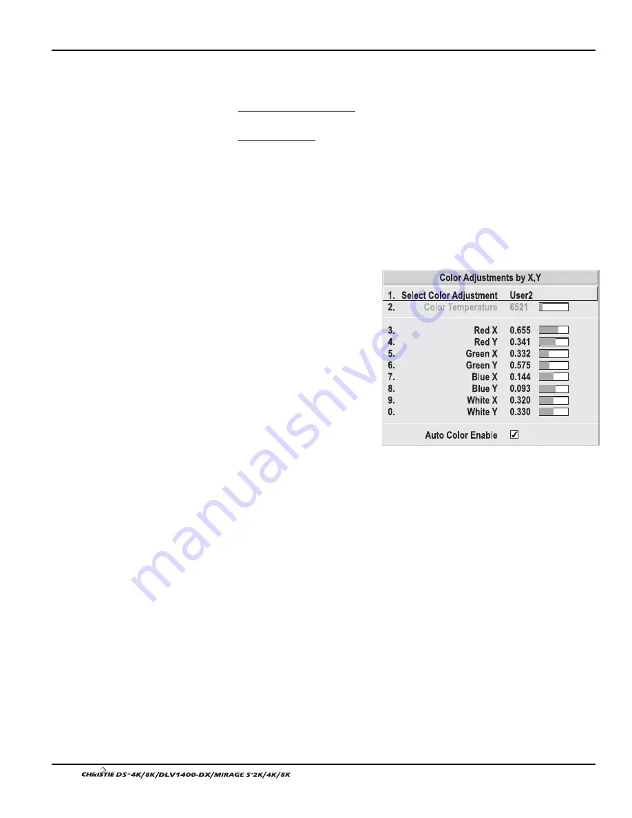
COLOR ADJUSTMENT BY X,Y:
Use
this submenu if you want to alter,
add or copy a color gamut (i.e.,
“color adjustment”). Controls in this
menu define the precise hue of each
primary color component (red,
green, blue, and white) used to
generate the millions of colors
produced in displays. The x/y
coordinates for each color define its
location on the standard CIE
chromaticity graph (see Figure
3.19)—changing either or both of
these numbers will change the hue of
the color, and relocate the “triangle”
for possible colors. For example,
changing the x/y coordinates for red will either move the color closer to orange or
closer to violet, which will in turn affect all displayed colors having a red component.
Adjust the slidebars or enter new specific coordinates as desired to define or change
up to four “User” color gamuts needed for your environment and applications. Apply
the new “User” color gamuts at any time in the Advanced Image Settings menu.
Figure 3.18. Customize Color Hue
Summary of Contents for DS+4K
Page 2: ......
Page 11: ...Section 2 Installation and Setup User s Manual 2 7 Figure 2 2 Vertical Offset Examples...
Page 12: ...Section 2 Installation and Setup 2 8 User s Manual Figure 2 3 Lens Vertical Offsets...
Page 14: ...Section 2 Installation and Setup 2 10 User s Manual Figure 2 5 Lens Horizontal Offsets...
Page 22: ......
Page 75: ...Section 3 Operation User s Manual 3 53 Figure 3 29 Customizing the Input Signal...
Page 92: ......
Page 102: ...Section 4 Maintenance 4 10 User s Manual Figure 4 8...
Page 106: ......
Page 120: ......
Page 122: ......
Page 124: ...Appendix C Serial Communication Cables C 2 User s Manual...
Page 126: ...Appendix D Throw Distance D 2 User s Manual...
Page 127: ...Appendix D Throw Distance User s Manual D 3...
Page 128: ...Appendix D Throw Distance D 4 User s Manual...
Page 129: ...Appendix D Throw Distance User s Manual D 5...
Page 130: ...Appendix D Throw Distance D 6 User s Manual...
Page 131: ...Appendix D Throw Distance User s Manual D 7...
Page 132: ...Appendix D Throw Distance D 8 User s Manual...
Page 133: ...Appendix D Throw Distance User s Manual D 9...
Page 134: ...Appendix D Throw Distance D 10 User s Manual...


