Section 3: Operation
User’s Manual 3-33
.
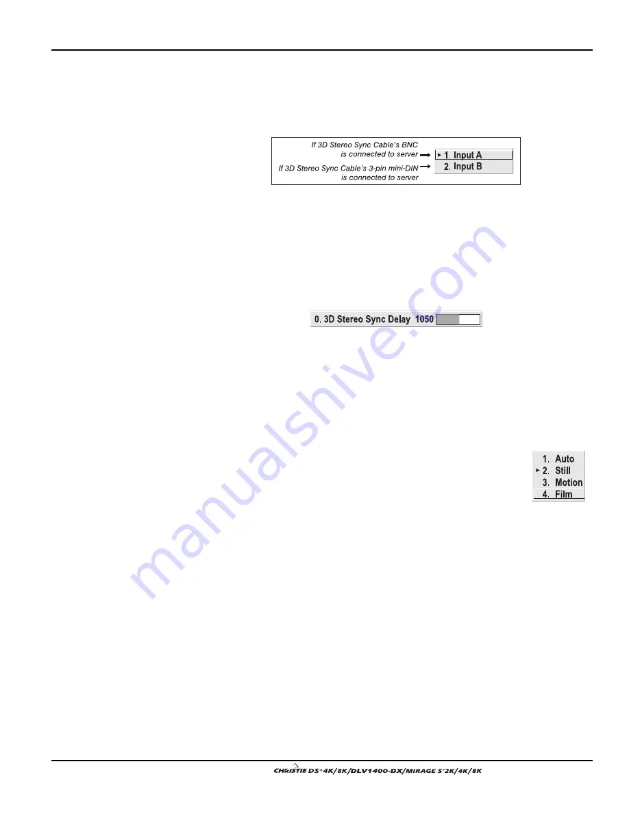
3D STEREO SYNC SELECT
—
Define which of the Mirage 3D Stereo Sync Cable’s
input connecters is routed to your server. Input A = BNC connector, Input B = 3-pin
mini-DIN connector. Use only if the cable is present. NOTE: Regardless of which
input is connected, the output routes to both outputs.
NOTE: See 3.9, 3D Images for a full explanation of 3D Stereo Sync Select use.
3D STEREO SYNC DELAY
—
Set when the L/R frames begin, defining the best
reference point for synchronizing the display with your glasses. Proper adjustment of
this delay should eliminate cross-talk and odd colors caused by timing differences
between the glasses and the projected display. Use this slidebar only if the Mirage 3D
Stereo Sync Cable is connected between the projector’s GPIO port and a server.
Slidebar values indicate the number of lines that are delayed.
NOTE: See 3.9, 3D Images for a full explanation of 3D Stereo Sync Delay use.
MOTION FILTER
—
This control is most useful for smoothing out moving images from
interlaced sources. In most cases the proper Motion Filter setting is automatically
determined according to the type of incoming source signal. However, if your source
is jittery and/or tearing you may wish to “force” a setting to ensure stable processing
for this source—if desired, override the default “Auto” setting by selecting the
appropriate motion filter:
1.
AUTO:
The projector will automatically use the correct motion
filter according to the incoming signal.
2.
STILL:
For static images with no motion, such as graphics from
a CD.
3.
MOTION:
For video images that did not originate from film, or
for moving computer-generated images.
4.
FILM:
For video images that originated from film. This will optimize image
quality and stability.
FILM MODE THRESHOLD
—
This setting determines how sensitively the projector can
detect if an incoming video signal originated from film or not.
DETAIL THRESHOLD
—
Use “Detail Threshold” to define at what frequency level the
“Detail” control will begin to magnify high frequencies, which adds details back into
the image. Raise the threshold to ignore more of these high frequencies, and lower the
threshold to magnify more of these frequencies. A setting of “0”, for example, means
no noise will be ignored and all will be magnified. An ideal detail threshold is one in
which high frequencies that are causing objectionable noise are not magnified when
using “Detail”, but frequencies which can help sharpen an overly-soft image are
magnified when using “Detail”.
Summary of Contents for DS+4K
Page 2: ......
Page 11: ...Section 2 Installation and Setup User s Manual 2 7 Figure 2 2 Vertical Offset Examples...
Page 12: ...Section 2 Installation and Setup 2 8 User s Manual Figure 2 3 Lens Vertical Offsets...
Page 14: ...Section 2 Installation and Setup 2 10 User s Manual Figure 2 5 Lens Horizontal Offsets...
Page 22: ......
Page 75: ...Section 3 Operation User s Manual 3 53 Figure 3 29 Customizing the Input Signal...
Page 92: ......
Page 102: ...Section 4 Maintenance 4 10 User s Manual Figure 4 8...
Page 106: ......
Page 120: ......
Page 122: ......
Page 124: ...Appendix C Serial Communication Cables C 2 User s Manual...
Page 126: ...Appendix D Throw Distance D 2 User s Manual...
Page 127: ...Appendix D Throw Distance User s Manual D 3...
Page 128: ...Appendix D Throw Distance D 4 User s Manual...
Page 129: ...Appendix D Throw Distance User s Manual D 5...
Page 130: ...Appendix D Throw Distance D 6 User s Manual...
Page 131: ...Appendix D Throw Distance User s Manual D 7...
Page 132: ...Appendix D Throw Distance D 8 User s Manual...
Page 133: ...Appendix D Throw Distance User s Manual D 9...
Page 134: ...Appendix D Throw Distance D 10 User s Manual...


