Section 3: Operation
User’s Manual 3-37
.
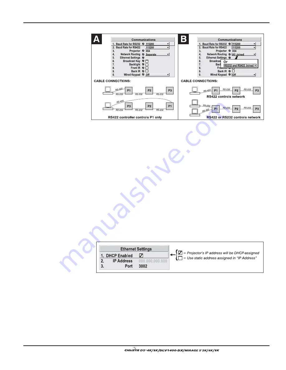
Figure 3.15. Using the “Network Routing” Option
RS232 AND RS422 JOINED:
Messages originating from an RS232 or RS422 controller
will be relayed to all RS232 ports. Any Ethernet communication, however, will not.
RS232 AND ETHERNET JOINED:
Messages to and from the RS232 ports will also be
relayed to the Ethernet port, and vice versa. Any RS422 communications will be
isolated.
ALL JOINED:
All messages reach all ports, regardless of type.
Ethernet Settings
(SUBMENU)
NOTES: 1) Recommended for network administrators only.
DHCP:
Enable this checkbox if you want a DHCP server to automatically change the
projector’s default IP address (0.0.0.0) to one that is valid and unique for use on the
current Ethernet network. On networks without a DHCP server, or to simply override
the automatic DHCP server function, delete the checkmark and enter the new “IP
Address” settings desired. Remember that only a 0.0.0.0 address will trigger the
DHCP addressing service and only when the DHCP checkbox is enabled.
IP ADDRESS:
Enter a valid and unique IP address for use on the network to which the
projector is currently connected. This address will overwrite any previous IP address
such as the projector’s factory-defined default (0.0.0.0), or one that has been assigned
by a DHCP server or other user. An IP address entered here remains in effect until it is
changed again.
PORT:
On some Ethernet networks, firewall restrictions may require that the port
number of the projector be changed from its default of 3002. If so, enter a new valid
port number here.
Summary of Contents for DS+4K
Page 2: ......
Page 11: ...Section 2 Installation and Setup User s Manual 2 7 Figure 2 2 Vertical Offset Examples...
Page 12: ...Section 2 Installation and Setup 2 8 User s Manual Figure 2 3 Lens Vertical Offsets...
Page 14: ...Section 2 Installation and Setup 2 10 User s Manual Figure 2 5 Lens Horizontal Offsets...
Page 22: ......
Page 75: ...Section 3 Operation User s Manual 3 53 Figure 3 29 Customizing the Input Signal...
Page 92: ......
Page 102: ...Section 4 Maintenance 4 10 User s Manual Figure 4 8...
Page 106: ......
Page 120: ......
Page 122: ......
Page 124: ...Appendix C Serial Communication Cables C 2 User s Manual...
Page 126: ...Appendix D Throw Distance D 2 User s Manual...
Page 127: ...Appendix D Throw Distance User s Manual D 3...
Page 128: ...Appendix D Throw Distance D 4 User s Manual...
Page 129: ...Appendix D Throw Distance User s Manual D 5...
Page 130: ...Appendix D Throw Distance D 6 User s Manual...
Page 131: ...Appendix D Throw Distance User s Manual D 7...
Page 132: ...Appendix D Throw Distance D 8 User s Manual...
Page 133: ...Appendix D Throw Distance User s Manual D 9...
Page 134: ...Appendix D Throw Distance D 10 User s Manual...


