Section 3: Operation
3-16
User’s Manual
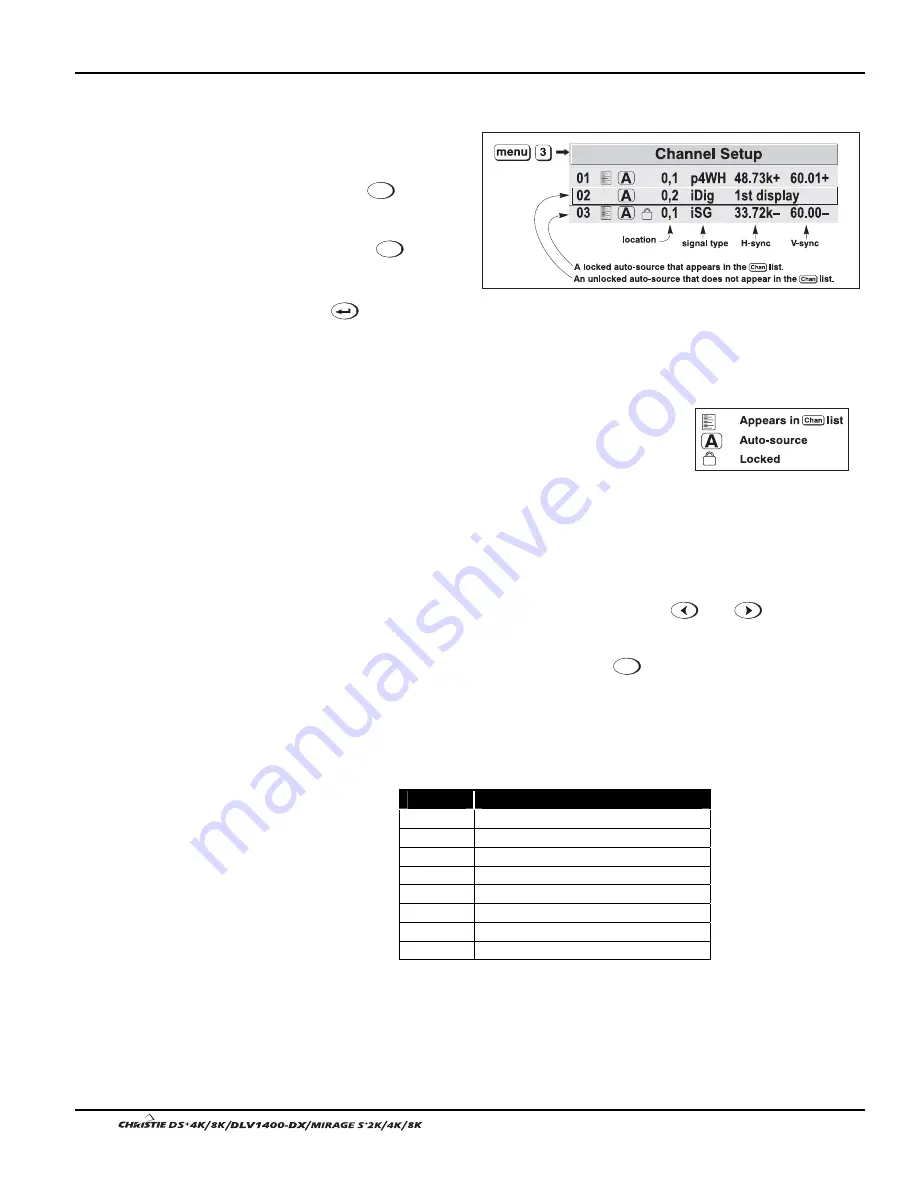
All available channels are listed in the Channel Setup menu, which describes how
each channel can be accessed and which serves as the gateway for editing, copying
and deleting channels.
From the presentation
level press
Menu
to display
the Main menu. To
display the Channel Setup
menu, press
3
, or
move the highlight to the
Channel Setup option and
press
. The Channel
Setup menu will appear
(see sample at right), with
the active channel highlighted.
WHAT APPEARS IN CHANNEL SETUP MENU?
This menu
lists all channels defined so far and indicates where they
are connected on the input panel. The far left column lists
channel numbers currently defined. The values in the far
right columns indicate horizontal and vertical
frequencies—if someone has defined a name for this channel, it appears here instead.
Remaining columns contain details pertaining to each channel setup, such as its
switcher number (always 0 = projector), slot location, a variety of icons indicating
access to each channel, and an abbreviated description of each signal type. See Editing
a Channel Setup for details.
NOTE: If you have more than a handful of channels, use
and
to see the
remaining channels not visible in the initial display of channels.
SIGNAL TYPE —
Either channel list, whether the
Channel
key list or the Channel Setup
menu, identifies signal types in a shortened form as defined below. These descriptors
indicate what signal information the projector uses to identify a match for a given
channel, and are preceded by either an “i” (interlaced signals) or “p” (progressive
signal“). See Table 3.2.
Table 3.2. Abbreviations for Signal Type
Abbrev.
Signal Type
4WH
Composite (4 wire) on HC input
4WV
Composite (4 wire) on V input
SG Sync-on-green
5W Separate
H,V
5WR
Separate H,V swapped
SVid S-Vid
CVid Composite
Video
Dig Digital
What
Channels
'
Are Defined So Far?
Figure 3.9. All Channels Appear in the
Channel Setup Menu
Summary of Contents for DS+4K
Page 2: ......
Page 11: ...Section 2 Installation and Setup User s Manual 2 7 Figure 2 2 Vertical Offset Examples...
Page 12: ...Section 2 Installation and Setup 2 8 User s Manual Figure 2 3 Lens Vertical Offsets...
Page 14: ...Section 2 Installation and Setup 2 10 User s Manual Figure 2 5 Lens Horizontal Offsets...
Page 22: ......
Page 75: ...Section 3 Operation User s Manual 3 53 Figure 3 29 Customizing the Input Signal...
Page 92: ......
Page 102: ...Section 4 Maintenance 4 10 User s Manual Figure 4 8...
Page 106: ......
Page 120: ......
Page 122: ......
Page 124: ...Appendix C Serial Communication Cables C 2 User s Manual...
Page 126: ...Appendix D Throw Distance D 2 User s Manual...
Page 127: ...Appendix D Throw Distance User s Manual D 3...
Page 128: ...Appendix D Throw Distance D 4 User s Manual...
Page 129: ...Appendix D Throw Distance User s Manual D 5...
Page 130: ...Appendix D Throw Distance D 6 User s Manual...
Page 131: ...Appendix D Throw Distance User s Manual D 7...
Page 132: ...Appendix D Throw Distance D 8 User s Manual...
Page 133: ...Appendix D Throw Distance User s Manual D 9...
Page 134: ...Appendix D Throw Distance D 10 User s Manual...


