Section 3: Operation
3-64
User’s Manual
Canceling Brightness Uniformity
If you do not want to use or apply Brightness Uniformity settings, delete the
checkmark from the “Uniformity Enable” checkbox at the top of the Brightness
Uniformity menu.
Christie Edge Blending is an innovative set of software functions that can quickly and
easily blend white levels along the edges of multiple adjacent projected images to
create a single seamless larger image.
What is a Blend?
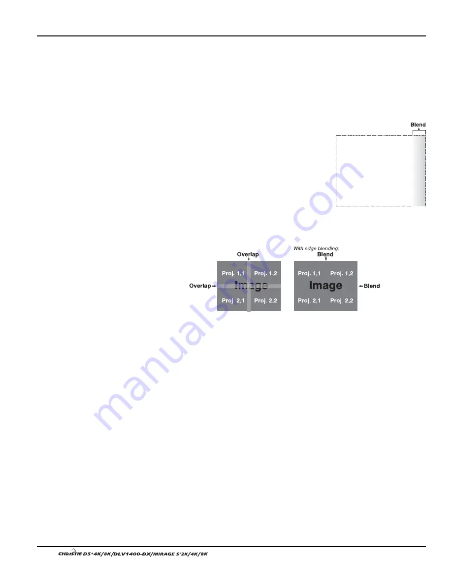
In simple terms, a blend appears as a gradient strip along
an edge of a projected image. It is darkest along the
extreme edge of the image, and lightens nearer to the
rest of the image (see right).
How Are Blends Used?
In multiple-projector walls, complementary blends
between neighboring images can compensate for the
extra “brightness” or intensity where these edges overlap. By controlling blend width
and other properties, you can achieve uniformity across the group of images. Visible
overlaps will disappear:
Figure 3. 36. Edge Blending Concept
For best results, use the same projector model and type throughout your display wall.
In addition, avoid high-gain screens whenever possible—the optical performance of
such screens demands minimal image offset, thus projectors must be located very
close to one another.
Edge blending software controls are located in the 2-page Edge Blending submenu—
access via Configuration menu, then go to the Geometry and Color menu and select
Edge Blending. The More option opens the second page of the Edge Blending
submenu.
Main Functions
Use Edge Blending controls to set the precise width, shape and midpoint you need to
blend overlapping edges together smoothly.
Blend Width
determines how much area is used for blending along an
overlapping edge. Slidebar values represent the number of 8-pixel steps used
for the blend. For example, a setting of “3” creates a blended edge 24 pixels
wide. A setting of “0” signifies no blending. For best results in most
applications, use a blend width of 16-48 steps (128-384 pixels).
Ranges: 0-80 horizontal, 0-60 vertical.
Edge Blending
'
Summary of Contents for DS+4K
Page 2: ......
Page 11: ...Section 2 Installation and Setup User s Manual 2 7 Figure 2 2 Vertical Offset Examples...
Page 12: ...Section 2 Installation and Setup 2 8 User s Manual Figure 2 3 Lens Vertical Offsets...
Page 14: ...Section 2 Installation and Setup 2 10 User s Manual Figure 2 5 Lens Horizontal Offsets...
Page 22: ......
Page 75: ...Section 3 Operation User s Manual 3 53 Figure 3 29 Customizing the Input Signal...
Page 92: ......
Page 102: ...Section 4 Maintenance 4 10 User s Manual Figure 4 8...
Page 106: ......
Page 120: ......
Page 122: ......
Page 124: ...Appendix C Serial Communication Cables C 2 User s Manual...
Page 126: ...Appendix D Throw Distance D 2 User s Manual...
Page 127: ...Appendix D Throw Distance User s Manual D 3...
Page 128: ...Appendix D Throw Distance D 4 User s Manual...
Page 129: ...Appendix D Throw Distance User s Manual D 5...
Page 130: ...Appendix D Throw Distance D 6 User s Manual...
Page 131: ...Appendix D Throw Distance User s Manual D 7...
Page 132: ...Appendix D Throw Distance D 8 User s Manual...
Page 133: ...Appendix D Throw Distance User s Manual D 9...
Page 134: ...Appendix D Throw Distance D 10 User s Manual...


