Section 2: Installation and Setup
User’s Manual 2-15
.
As an alternative to the projector’s keypad or remote, you may wish to communicate
with the projector using a PC or other controller. Such a device sends commands and
receives feedback via serial links (RS232 and RS422), Ethernet or GPIO
communications to the projector, all described below.
As desired, direct the projector’s IR remote keypad towards the display screen or the
projector’s IR sensors. Alternatively, connect a wired (tethered) version of the remote
to the 3.5mm RCA jack labeled as
REMOTE
on the projector’s input panel. Note that
response to a wired keypad must also be enabled in the Communications menu—see
3.6, Adjusting System Parameters and Advanced Controls for more information.
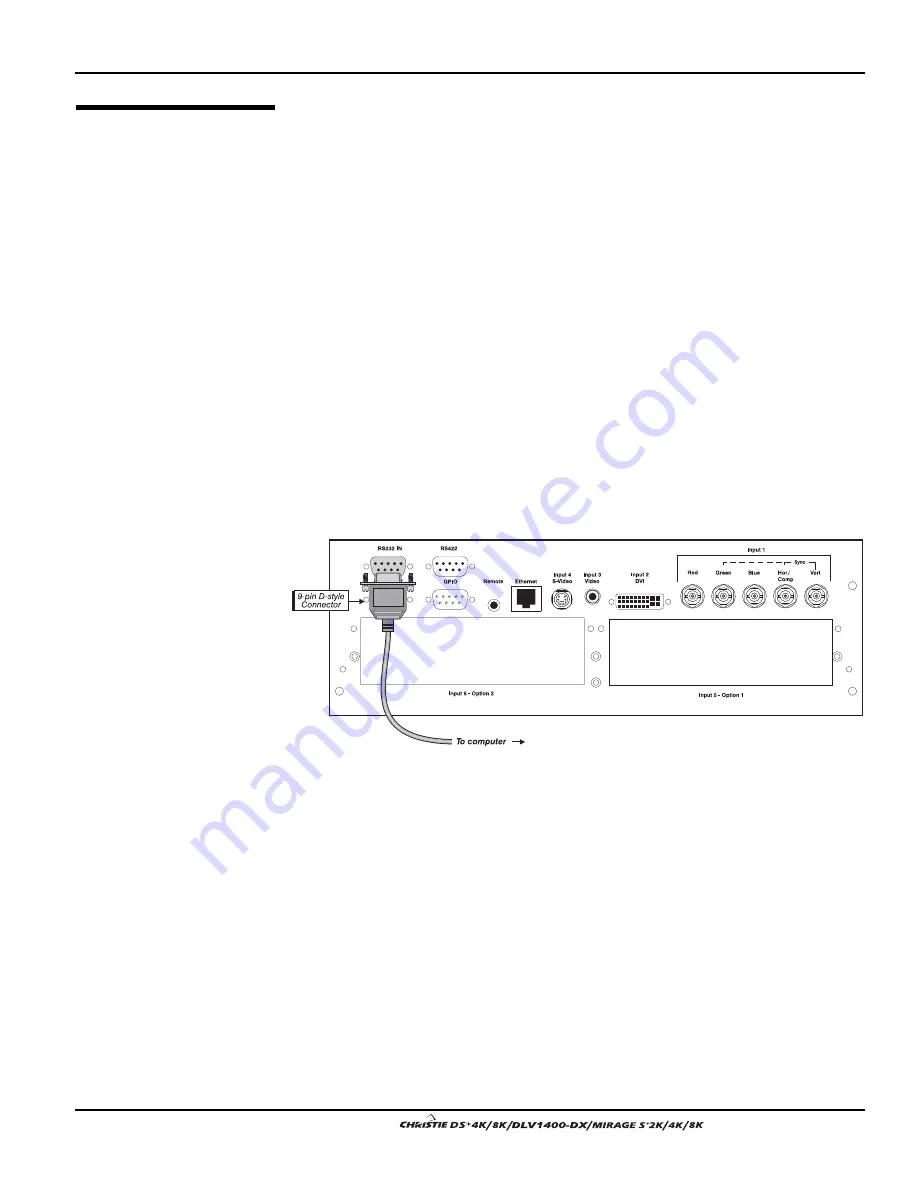
There are two types of serial ports available on the projector: RS232 and RS422. You
can connect a device with a serial interface, such as a computer to either of these
connectors (not both) and control the projector remotely by entering specific serial
communication commands.
Connecting RS-232
The two 9-pin DIN connectors labeled RS232 IN and RS232 OUT on the input panel
are dedicated to serial communication. Using the appropriate serial communication
cables (see Appendix C) connect the controlling source, such as a personal computer
to the RS232 IN connector. Then set the baud rate to match that of the computer.
Refer to Section 3 for details on changing the projector’s baud rate.
Figure 2.11. Connecting RS232
If you want to connect multiple projectors in a network with serial communication,
connect the controlling source to the RS232 IN connector of the first projector in the
network. Then take another serial communication cable and connect one end to the
RS232 OUT connector and the other end to the RS232 IN connector of the next
projector. Continue this pattern of connection with all projectors in the network. The
last projector in the network will only have a connection to the RS232 IN connector.
2.4 Connecting
Communications
Remote
Keypads
'
Serial
Port
Connections
'
Summary of Contents for DS+4K
Page 2: ......
Page 11: ...Section 2 Installation and Setup User s Manual 2 7 Figure 2 2 Vertical Offset Examples...
Page 12: ...Section 2 Installation and Setup 2 8 User s Manual Figure 2 3 Lens Vertical Offsets...
Page 14: ...Section 2 Installation and Setup 2 10 User s Manual Figure 2 5 Lens Horizontal Offsets...
Page 22: ......
Page 75: ...Section 3 Operation User s Manual 3 53 Figure 3 29 Customizing the Input Signal...
Page 92: ......
Page 102: ...Section 4 Maintenance 4 10 User s Manual Figure 4 8...
Page 106: ......
Page 120: ......
Page 122: ......
Page 124: ...Appendix C Serial Communication Cables C 2 User s Manual...
Page 126: ...Appendix D Throw Distance D 2 User s Manual...
Page 127: ...Appendix D Throw Distance User s Manual D 3...
Page 128: ...Appendix D Throw Distance D 4 User s Manual...
Page 129: ...Appendix D Throw Distance User s Manual D 5...
Page 130: ...Appendix D Throw Distance D 6 User s Manual...
Page 131: ...Appendix D Throw Distance User s Manual D 7...
Page 132: ...Appendix D Throw Distance D 8 User s Manual...
Page 133: ...Appendix D Throw Distance User s Manual D 9...
Page 134: ...Appendix D Throw Distance D 10 User s Manual...


