Section 3: Operation
User’s Manual 3-3
.
Laser radiation is emitted from the laser diode in the remote. Do not look
directly into the beam of the remote.
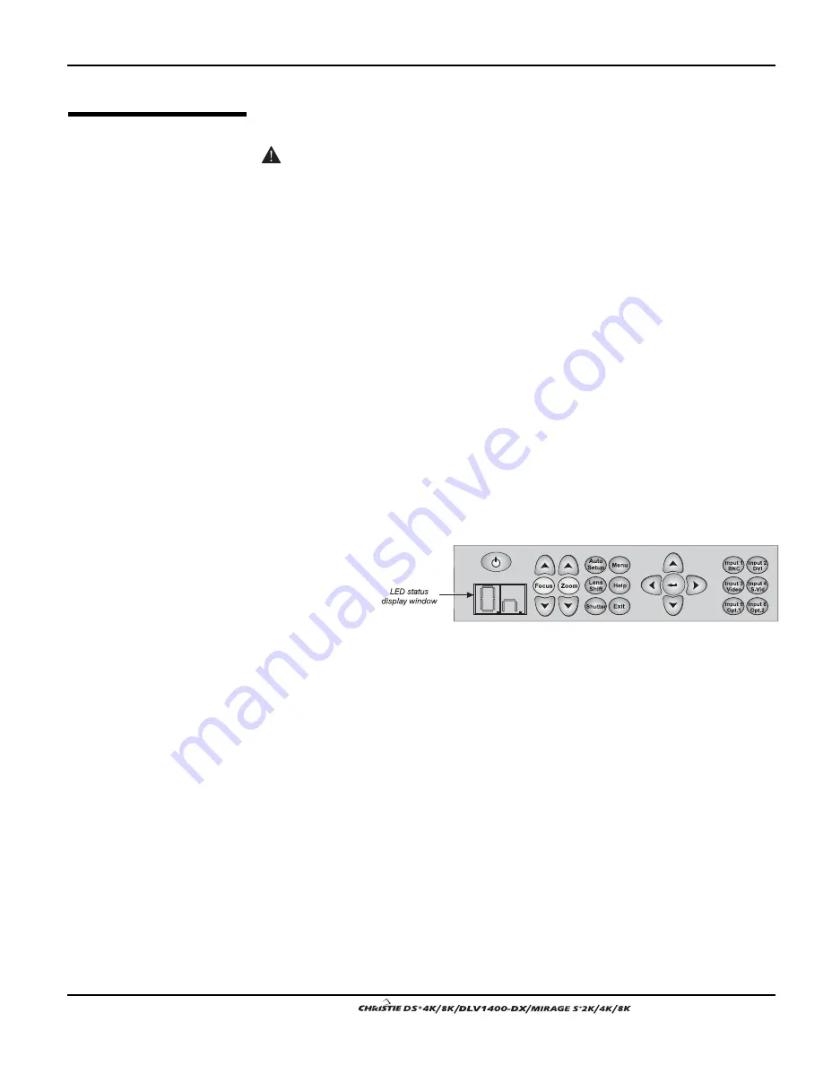
The projector is typically controlled using one of the following keypads:
•
Built-in Keypad located at the back of the projector
•
Remote Keypad for tethered or tetherless control up to 100 feet away
(includes cable for use as a wired remote)
While each of the keypads provides complete control of the projector, they differ
slightly in their arrangement of keys and in what functions can be accessed directly
with a key press rather than requiring use of the menu system. You may find one
keypad more convenient than another for your specific installation and application.
NOTE: This keypad has a single IR protocol and can be converted to a wired remote
by connecting the cable provided with the projector to the RCA jack labeled as
REMOTE
on the input panel.
To control the projector when signals from a remote keypad cannot reach the
projector, use the projector’s built-in keypad. The nearby LED display provides
feedback indicating current status and activities of the projector. Because the built-in
keypad has fewer
keys than the
remote keypad,
certain projector
functions are
accessible only
through the menu
system rather
than via a direct key.
Refer to the key descriptions provided for the IR remote – see Figure 3.3.
The IR remote keypad controls the projector by way of wireless communications from
a battery-powered infrared (IR) transmitter. Use the IR remote keypad the same way
you would use a remote keypad supplied with a TV or VCR. When making key
presses, direct the keypad either toward the screen or toward the front or rear of the
projector. One of the two IR sensors on the projector will detect the signals and relay
the commands for internal processing.
3.2 Using
the
Remote or Built-
In
Keypad
Keypad Commands
'
Built-in
'
Figure 3.2. Built-in Keypad
IR
Remote
'
Summary of Contents for DS+4K
Page 2: ......
Page 11: ...Section 2 Installation and Setup User s Manual 2 7 Figure 2 2 Vertical Offset Examples...
Page 12: ...Section 2 Installation and Setup 2 8 User s Manual Figure 2 3 Lens Vertical Offsets...
Page 14: ...Section 2 Installation and Setup 2 10 User s Manual Figure 2 5 Lens Horizontal Offsets...
Page 22: ......
Page 75: ...Section 3 Operation User s Manual 3 53 Figure 3 29 Customizing the Input Signal...
Page 92: ......
Page 102: ...Section 4 Maintenance 4 10 User s Manual Figure 4 8...
Page 106: ......
Page 120: ......
Page 122: ......
Page 124: ...Appendix C Serial Communication Cables C 2 User s Manual...
Page 126: ...Appendix D Throw Distance D 2 User s Manual...
Page 127: ...Appendix D Throw Distance User s Manual D 3...
Page 128: ...Appendix D Throw Distance D 4 User s Manual...
Page 129: ...Appendix D Throw Distance User s Manual D 5...
Page 130: ...Appendix D Throw Distance D 6 User s Manual...
Page 131: ...Appendix D Throw Distance User s Manual D 7...
Page 132: ...Appendix D Throw Distance D 8 User s Manual...
Page 133: ...Appendix D Throw Distance User s Manual D 9...
Page 134: ...Appendix D Throw Distance D 10 User s Manual...


