Chopin Mixolab Maintenance Manual Download Page 135

Chapter 4   Spare parts

135

Maintenance manual 

MM-MIXO-EN Ind. 0


04/2012

Mixolab

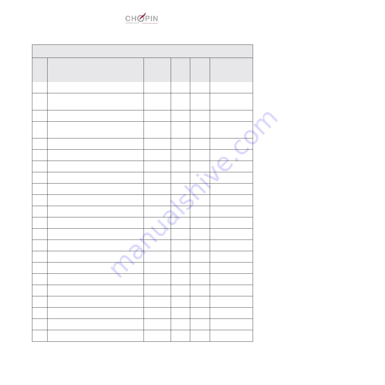
Mixolab - Compressor and CPU support

item

Description

CHOPIN 

Part no.

Qty

Min. 

qty p. 

order

Note

1

INDUCTOR - WIRED, 1.2A ARMATURE 

MIX 12

1

2

SCREW - HSHC M5X12, STAINLESS 
STEEL

2

3

WASHER - RLC 5MM DIA

2

4

SOLENOID VALVE - WIRED, 
COMPRESSOR

MIX 183

1

5

WASHER - RLC 4X10MM DIA

2

6

SCREW - HSHC 3X6I

7

COMPRESSOR - MEMBRANE 

MIX 6

1

8

SUPPLY BOARD

SEN 150

1

9

SCREW - HSHC M3X6, STAINLESS STEEL

4

10

SUPPLY BOARD - 24 V

CB 159

1

11

CPU BOARD - MIXOLAB

SEN 162

1

12

SCREW - HSHC M3X6, STAINLESS STEEL

4

13

WASHER - RLC 5MM DIA

2

Summary of Contents for Mixolab

Page 1: ...n Berthelot Z I du Val de Seine 92396 Villeneuve La Garenne cedex France T l 33 0 1 41 47 50 88 Fax 33 0 1 47 92 28 27 www chopinservice com www chopin fr Mixolab Maintenance manual Ref MM MIXO EN Ind...

Page 2: ......

Page 3: ...strations are not contractual their only target being to bring assistance for troubleshooting and repairing the Mixolab Use duplication or disclosure of subject data for any purpose other than relatin...

Page 4: ......

Page 5: ...al information 7 1 Operating conditions 9 2 Precautions related to tests 10 3 Control and maintenance 11 Chapter 2 Troubleshooting 15 1 Method 17 2 Fault handling 18 3 Interconnection diagrams 27 Chap...

Page 6: ...Mixolab 6 Maintenance manual MM MIXO EN Ind 0 04 2012...

Page 7: ...7 Maintenance manual MM MIXO EN Ind 0 04 2012 Mixolab Chapter 1 OPERATION MAINTENANCE REMINDERS ADDITIONAL INFORMATION...

Page 8: ...8 Maintenance manual MM MIXO EN Ind 0 04 2012 Mixolab...

Page 9: ...ght for severals hours a day The Mixolab must not be placed right up against a wall Leave sufficient space to ensure proper ventilation The working area shall also take into account all subsidary oper...

Page 10: ...r temperature of the cooling water circuit must be in a range between 15 C and 20 C 2 Precautions related to tests Tests on the Mixolab must always be conducted with great care All necessary instructi...

Page 11: ...howing the Mixolab mimic diagram monitors operation of the main modules of the device In order to access this mimic diagram click on Configuration and then on Maintenance Colour LED status Meaning Not...

Page 12: ...enu allows to download a new version of the embedded software This operation can only be performed by entitled agents see Operation 11 1 Updating the Mixolab software page 90 Dough temperature sensor...

Page 13: ...l chart is highly recommended A regular control of the test results on known flour samples allows to detect errors leading to possible failures quality of testing opera tions of testing environment or...

Page 14: ...14 Maintenance manual MM MIXO EN Ind 0 04 2012 Mixolab Chapter 1 Operation Maintenance reminders additional information...

Page 15: ...15 Maintenance manual MM MIXO EN Ind 0 04 2012 Mixolab Chapter 2 TROUBLESHOOTING...

Page 16: ...16 Maintenance manual MM MIXO EN Ind 0 04 2012 Mixolab...

Page 17: ...ey may help to locate failures Of course in case of difficulty or doubt the engineering services of CHOPIN Technologies are available to try to solve the problem via phone fax or e mail If this fails...

Page 18: ...etting If the circuit is blocked find where by dis mantling it piece after piece Wrong temperature information Calibrate bowl temperature measurement Replace temperature sensor if the problem is not s...

Page 19: ...rectify No output flow check hydraulic connection solenoid valve operation using maintenance screen flow controller setting If the circuit is blocked find where by dis mounting it piece after piece W...

Page 20: ...Tank temperature too low Heating time out after 15 min of heating absence tank T 90 of setpoint Confirm on maintenance screen Wrong temperature indication Calibrate the tank temperature measurement C...

Page 21: ...s bearings clean or replace Remove covers disconnect the motor and find the origin of hard points readjust the alignment between motor and bowl block if the problem is not solved find the failed part...

Page 22: ...two kneading arms bearings clean or replace as necessary Remove covers and move the transmission by hand using the motor encoder disc If the assembly is jammed or rotates uneasily readjust the alignme...

Page 23: ...or torquemeter etc and replace it Speed measurement problem readjust the inductive sensor replace it if necessary If the problem is not solved replace the motor op 6 op 6 3 op 6 3 ERR 53 Motor speed c...

Page 24: ...een two tests Test the sensor using the maintenance menu if the fault is continuous replace the sensor magnet or sensor if the fault is intermittent check mainly the elements fixing points magnet and...

Page 25: ...itch is activated ON each time the piston is at the back If the piston does not move or stops moving too early there is a mechanical failure or a motor failure check motor wiring and connections then...

Page 26: ...screen drain the tank between two tests op 11 7 2 Abnormal evolution of the bowl block temperature This could be due to Inversion of input and output hoses on cooling circuit Incorrect setting of cool...

Page 27: ...g Thermocouple Dough Magnetic holder Cover safety switch Bowl locking switch Tank Front panel light Bowl temp sensor Supply board Heating resistors Heat safety Thermal safety Heating resistor Level de...

Page 28: ...nductor cable MIX 12 To terminal block cable MIX 134 To metering pump motor microswitch solenoid valve cable MIX 125 To tank temperature Pt100 cable MIX 135 To locking switch cable MIX 131 To tank tem...

Page 29: ...electronic board support plate MIX 83 Wires soldered See detail D Connection of earth wires CB 37 with cable terminations STARFIX CN 92 75 D17 to be soldered on the connector terminals with the wires...

Page 30: ...ubleshooting Maintenance manual MM MIXO EN Ind 0 04 2012 Mixolab Hydraulic circuit Water pump Compressor Filling block Compressor solenoid valve Water injection nozzle Tank Tank water level Vent Vent...

Page 31: ...31 Maintenance manual MM MIXO EN Ind 0 04 2012 Mixolab Chapter 3 REPAIR...

Page 32: ...32 Maintenance manual MM MIXO EN Ind 0 04 2012 Mixolab...

Page 33: ...y envi ronment with a complete set of standard tools in addition to the mentioned special tooling repair operations should be carried out with care by competent personnel with adequate qualification s...

Page 34: ...ties CABL 2 Bowl block assembly Operation 2 1Dismantling installing the resistors and the temperature limiter Thermal com pound grease Silicone mastic TECH Operation 2 2Dismantling installing the wire...

Page 35: ...pump pliers TECH Operation 4 7Dismantling installing the equipped metering pump Cable ties MEC Operation 4 8Dismantling installing the water injection nozzle MEC 5 Pneumatic components Operation 5 1Di...

Page 36: ...Operation 10 1Dismantling installing the power supply board MEC 11 Adjustments and checks for the Mixolab Operation 11 1Updating the Mixolab software TECH Operation 11 2Calibration the bowl and therm...

Page 37: ...TECH Operation 11 12Checking characteristics of a Pt100 temperature probe Multimeter TECH Operation 11 13Checking the heating circuit Multimeter TECH Operation 11 14Checking the supply voltages Voltm...

Page 38: ...38 Chapter 3 Repair Maintenance manual MM MIXO EN Ind 0 04 2012 Mixolab...

Page 39: ...Chapter 3 Repair 39 Maintenance manual MM MIXO EN Ind 0 04 2012 Mixolab 2 Instructions See following pages...

Page 40: ...ee attachment screws of the right casing C 4 Pull upwards the filling block with its cover to remove it D take care not to loose the cover during the operation 5 Unscrew the plastic nut E attaching th...

Page 41: ...rd 4 Undo the left and right attachment screws of the casing C on the bowl 5 Remove the water injection nozzle D 6 Remove the tube ball joint from the central casing E then remove the tube 7 Open the...

Page 42: ...J of the magnetic holder from the CPU board then cut the cable tie 12 Unplug connector K of the magnetic detector from the CPU board then cut the cable tie 13 Slide upwards the central casing and remo...

Page 43: ...connectors with help of a flat screwdriver for unlock ing Pull out the connectors not the wires b Pneumatic connections Pneumatic connections are not easy to release the use of a flat screwdriver wil...

Page 44: ...s firmly on the fitting ring while pulling at the same time on the tube A Proceed the same way for the hydraulic tube located under the Mixolab B When re connecting the hydraulic tubes in order to avo...

Page 45: ...minal block insert a narrow tool in the hole close to the connection and pull out the wire B 3 Undo the attachment screws of the filter switch Pull out the switch from the chassis C 4 Replace the filt...

Page 46: ...ft side unit viewed from its front 2 Loosen the feet lock nuts A 3 Unscrew the anti vibration feet 4 Replace the feet When installing the unit its horizontality shall be adjusted by mean of a spirit l...

Page 47: ...remove it A take care not to loose the cover during the operation 2 Dismount the cover by removing its hinge axle from the filling cup B Refitting the filling block does not require any particular ins...

Page 48: ...on the central casing then remove the LED from the casing B 4 Cut the wires at connector level remove the connector then slide out the cable through the casing hole When mounting a new 3 colour LED ta...

Page 49: ...3 Remove the wires from the resistors and the temperature lim iter 4 Remove the silicone mastic which seals each resistor and the temperature sensor to the white plastic plate B and C 5 Extract the h...

Page 50: ...e op 2 3 on the white plastic plate 17 Replace all heating resistors in the proper order see figure opposite while taking care to first coat the new resistors with compound grease before inserting the...

Page 51: ...e C 5 Coat the new sensor with silicon heat conductive compound and insert it into the heating plate 6 Put some silicone mastic on the temperature sensor visible portion at the white plastic plate lev...

Page 52: ...e thermocouple support from the white plas tic plate Install the new thermocouple support by screwing it on the white plastic plate then screw the fixation nut on the support without blocking it 5 Ada...

Page 53: ...hermocouple connector 2 By using a narrow screwdriver disconnect the four wires from the connector A 3 Undo the screw fixing the thermocouple socket to the chassis B Refitting the thermocouple micro c...

Page 54: ...the new mag netic sensor 8 Put in place the new magnetic sensor in the stuffing box body The detector must be positioned 0 5 mm in front of the plate where the stuffing box is installed C 9 Screw the...

Page 55: ...nnector of the locking switch cable D on the CPU board 6 Undo the two attachment screws of the switch E on the alu minium block 7 Make the connector pass through the chassis hole remove first the wire...

Page 56: ...es shall be mounted at the inner sides of the plates then turn the plates up side down and press on the plates until the bearings are fully inserted in their hole G do not use a mallet The bearing fla...

Page 57: ...up the cover deflector 3 Undo the two attachment screws of the gas spring protecting plate B 4 Remove the gas spring protecting plate Refitting the new gas spring protection does not require any parti...

Page 58: ...ver during the operation to prevent its fall 3 Remove the cover turn up the cover deflector in vertical posi tion then push the latter downward to disengage it from its axles C 4 Laterally move the de...

Page 59: ...s spring protective plate see op 3 1 3 Remove the circlips from the gas spring upper axle B then rotate the gas spring to the front 4 Remove the circlips from the gas spring lower axle 5 Remove the ga...

Page 60: ...e cen tral casing B 4 Extract the cover support and the cover from the central cas ing by moving them downward 5 Undo the two attachment screws of the coded magnet detector C and remove the detector R...

Page 61: ...osen the setscrew locking the magnetic holder A 3 Extract the magnetic holder from the support by moving it downward B Refitting the new magnetic holder does not require any particular instruction Mak...

Page 62: ...page 4 Disconnect the earth terminal from the chassis C 5 Unplug all hydraulic connections on the tank 6 Cut the cable ties of the electrical cables on the tank 7 Unplug the connector of the double l...

Page 63: ...ar instruction Note Do not omit to re attach the electrical wires with cable ties Replacing the hydraulic tubes is recommended 4 Hydraulic components Operation 4 1 Dismantling installing the equipped...

Page 64: ...2 Unplug the connector of the double level detector on the CPU board A 3 Undo the three fixation screws of the tank cap B then remove the tank cap 4 Unscrew the detector from the cap by mean of an op...

Page 65: ...he double level detector on the CPU board A 4 Undo the 3 fixation screws of the tank cap B then remove the tank cap 5 Cut the two cable ties flush along the buffer tank length 6 Unplug the hydraulic c...

Page 66: ...e resistor from the thimble A 4 Unscrew the temperature limiter B Refitting the new wired tank resistor does not require any particular instruction Note Re apply some silicone mastic for blocking the...

Page 67: ...sensor from the thimble A Refitting the new temperature sensor does not require any particu lar instruction Note Re apply some silicone mastic for blocking the temperature sensor inside the thimble B...

Page 68: ...otect ing cover B remove the cover 4 Unscrew the attachment screw of the valve connector C then remove the valve connector 5 Unscrew the knurled nut attaching the solenoid valve head D if necessary us...

Page 69: ...king the pump to the tank B 4 Undo the two attachment nuts C of the pump and remove it Refitting the new equipped pump does not require any particular instruction Notes Replacing the small hydraulic t...

Page 70: ...connect the tube form the water injection nozzle by press ing the fitting ring while pulling at the same time on the tube A Refitting the new water injection nozzle does not require any particular ins...

Page 71: ...essor connector from the CPU board B 4 Undo the attachment screw of the ground cable C on the compressor 5 Cut the rubber support feet D from under the compressor support plate and remove the compress...

Page 72: ...on 3 Unplug the wiring solenoid valve connector from the CPU board B 4 Unscrew the two attachment screws of the solenoid valve C and remove the valve Refitting the new solenoid valve does not require...

Page 73: ...or from the CPU board A cut as needed the cable ties 3 Undo the screw attaching the ground wire on the motor B and remove the wire 4 Undo the two attachment screws of the encoder wheel C then remove i...

Page 74: ...tachment screws of the motor G and remove the motor Notes While removing the motor attachment screws hold the motor and take care it does not fall over due to its weight Check that the detector wheel...

Page 75: ...the two attachment screws of the encoder wheel A then remove it 3 Loosen the set screw of the encoder wheel then extract the wheel hub B Refitting the new encoder disc does not require any particular...

Page 76: ...ble terminals of the inductive sensor from the con nector 4 Hold the sensor rear nut with an open end wrench and loosen the front nut 5 Remove the inductive sensor The sensor shall be re installed so...

Page 77: ...collect the key C from the torquemeter axle For installing the coupling take care to following points The motor shaft shall be perfectly aligned with the torquemeter axle and driving the whole line sh...

Page 78: ...washer under the support 4 Slide the support along the torquemeter to remove it Refitting the new torquemeter support does not require any particular instruction When re installing the support the sup...

Page 79: ...ter support the support base shall be kept parallel to the chassis before tightening the screw place a gauge of the appropriate thickness same as washer s under the support other extremity C Before me...

Page 80: ...he cable tie holding the cable on the torquemeter support 4 Disconnect the torquemeter cable from the CPU board B 5 Extract cable terminals of the torquemeter cable from the con nector Refitting the n...

Page 81: ...C 8 Remove the distribution block by first raising it a little to free it from the pins then moving it lengthwise to release the axles from the couplings 9 Install the new distribution block by first...

Page 82: ...ofile is located at 10 mm approx from the back edge of the bowl see photo G 14 Tighten the couplings at bowl side thread locking with Loctite 222 15 Check the good rotation by manually turning the kne...

Page 83: ...he kneading arm coupling from the distribution block axle D 7 Remove the junction axle from the coupling 8 Put in place the junction axle in the new coupling 9 insert the coupling on the distribution...

Page 84: ...en the junction axles and the bowl plastic plate 14 For adjusting the kneading arms turn them until the nearest points of their profile is located at 10 mm approx from the back edge of the bowl see ph...

Page 85: ...ment screws of the USB board on the chassis with an Allen key C then remove the USB board assembly 5 Replace the USB board support assembly carefully re plug the two connectors on the CPU board 6 Rein...

Page 86: ...well as the central casing see op 1 2 2 Disconnect the inductor cable on the CPU board A 3 Undo the two attachment screws of the Inductor on the chassis B then remove the inductor Refitting the new in...

Page 87: ...B and remove the board 4 Replace the CPU board carefully re plug all connectors while respecting the previously recorder mounting order 5 Reinstall the left and right Mixolab casings see op 1 1 6 proc...

Page 88: ...tic sealant on the CPU board 4 Apply a little bit of silicone mastic on the thermocouple sensor and seal the new cabochon 5 Reinstall the left and right casings see op 1 1 9 Mixolab CPU board Operatio...

Page 89: ...attachment screws of the power supply board with an Allen key B then remove the board 4 Replace the power supply board carefully re mount the con nectors 5 Reinstall the right Mixolab casings see op...

Page 90: ...ess OK pops up C 4 Turn off the Mixolab from the On Off switch on its side D 5 Press OK on the dialog box Turn of the MIXOLAB A dialog box Turn on the MIXOLAB then press OK pops up E 6 Turn on the Mix...

Page 91: ...meter in the plain bowl into the hole provided A 4 Wait 10 min then read the temperature on the thermometer 5 Compare the thermometer temperature to the bowl tempera ture measured by the Mixolab B the...

Page 92: ...thermometer then validate by pressing OK 9 Click then ion the brown tab above the temperature setpoint to access to access to the modification window of the dough temperature E 10 In dialog box Passwo...

Page 93: ...to 30 C Then let the temperature stabilize for at least 15 minutes 5 Place a thermometer at the tank filling orifice level A 6 Wait 10 min then read the temperature on the thermometer 7 Compare the th...

Page 94: ...alog box Password enter 1576 D 10 The dialog box Tank temp adjustment pops up enter the value read by the thermometer then validate by pressing OK 11 Turn off the unit and disconnect the mains 12 Re i...

Page 95: ...sing a sample said standard sample and import it to the equipment to be calibrated 2 Testing said comparison testing without temperature adjust ment 3 Determining the calibration rate using the temper...

Page 96: ...icking on the cross in the top right Testing without temperature adjustment First perform a comparison test on an X bowl 1 Access the Configuration menu then the Mainte nance menu 2 In the synoptic vi...

Page 97: ...alibrationra tes are set to 0 Return to previous step 1 1 Precautions before testing for doing this Note This test will be recorded in the Mixolab database and will be used in the calculation of the c...

Page 98: ...tenance menu 2 In the synoptic view of the Maintenance menu click on Tes ting without temperature adjustment A see illustration below enter 1576 this manipulation allows to activate the Calibrating th...

Page 99: ...s aimed at choosing the standard test by reference to a comparison test The upper graph shows the standard test and the lower graph shows the one to be compared to see red circle below 11 Adjustments...

Page 100: ...tion rate to the bowl being used for that purpose just click on the green validation button as shown on the illustration below and follow the following steps Click on YES the rate is assigned to the b...

Page 101: ...sure the calibration rate is well taken into account in the Mixolab Therefore check the calibration rates in the Calibra tion menu For doing so return from here and follow the step 1 1 Precaution bef...

Page 102: ...hen close the window In unticking this option the calibrating of tempe rature is activated 3 Prepare and launch the test with the bowl just being calibra ted This time the temperature adjustment is ap...

Page 103: ...0 5 C The dough temperature with temperature adjust ment can be above or below the standard dough temperature Terefore you must make a calibration rate adjustment previously calculated For doing this...

Page 104: ...djustment The calibration rate adjusted we must transfer it to the Mixolab i e enter it by hand in the Calibrating the temperature menu 3 Activate the Calibrating the dough temperature menu then redo...

Page 105: ...tion rate to the mixolab by clic king on the purpose double arrow 7 Close the Calibrating the temperature menu by clicking on the red cross 8 Control and check if the adjusted calibration rate transfe...

Page 106: ...ply the tachometer directly to the motor shaft end C 7 Read the speed measured with the tachometer it should be 960 rpm 24 i e 80 rpm 1 at kneading arm level or 3000 rpm 24 i e 250 rpm 1 at kneading a...

Page 107: ...supply appears B 3 Check the function of the draining hose C water should come out this confirms that water circulates into the cooling circuit 4 Let the cooling circuit operate for 3 minutes this all...

Page 108: ...it 3 Click on solenoid valve icon B and start at the same time the chronometer 4 After 1 minute stop the solenoid valve and the chronometer 5 Measure the quantity of water in the vessel 6 If the amoun...

Page 109: ...1 minute The adjustment of the valve is performed with the MIXOLAB slightly tilted to easier the passage of the hand and the 1 minute flow test shall be performed with the MIXOLAB horizontal parallel...

Page 110: ...do not buckle the metal lic support and turn back 1 2 turn 3 Run the MIXOLAB program and acknowledge the error mes sage 4 Go to the maintenance menu 5 On the pump icon click on the corner coloured in...

Page 111: ...password 1576 then validate by clicking on OK 4 Click on Reset B 5 Enter the password 2508 then validate by clicking on OK 6 The calibration parameters resetting window pops up Click on Yes 7 Take a p...

Page 112: ...er it will redirect it to the nozzle Note The operation is not terminated as long as the green disc does not display ON The nozzle ejects now the 10ml of water hold the assembly Once operation complet...

Page 113: ...se to 30g Do not forget to perform two other tests then take the average H 3 Click on the brown corner to access to the pump characteris tics I 4 In the dialog box Pump check adjustment enter the pass...

Page 114: ...form the same operations as previously repeat the calibra tion operations from step 9 calibration for 10ml The measurements should be close to 25 The tolerance interval is 24 875 25 125 ml 3 Report th...

Page 115: ...n wire terminal and black wire terminal on connector No 3 A 4 Carefully record the number of beats D for the adjustment of the 2 5V b Adjusting the 1 8V 1 Proceed the same way for adjusting the voltag...

Page 116: ...e screw on the sensor e Final torque adjustment 1 Click on the brown corner G 2 Enter the password 1576 3 Complete the Torque adjustment table H with the values pre viously recorder I Validate by clic...

Page 117: ...alidate and close 3 Run a test with a flour whose main characteristics are known moisture hydration an hydration basis using the CHOPIN protocol 4 Stop the test after 10 min and record the torque C1 5...

Page 118: ...wl block temperature between terminals 1 or 3 and 2 or 4 Tank temperature between terminals 1 or 4 and 2 or 5 4 The resistance should be 100 at 0 C with a slope of 0 384 C i e for example for 25 C 100...

Page 119: ...sistance value equal to or around zero is normal an infinite resistance value indicates that the safety thermo stat is probably damaged 5 Check the insulation of each connection resistors and thermo s...

Page 120: ...b Presence of 230 Vac inside the unit 4 Check using a voltmeter all voltages on the power supply board mentioned on sketch below 5 Turn off the Mixolab and disconnect it 6 Re install the right casing...

Page 121: ...neutral 2 3 4 230V Phase Heating resistors tank 1 Resistor A 2 Th switch A 3 Th switch A 1 Resistor B Water 1 Water valve 2 24V RJ45 RS USB link Water level 1 Low level 2 GND 3 GND 4 Level 1 3 USB RS...

Page 122: ...122 Chapter 3 Repair Maintenance manual MM MIXO EN Ind 0 04 2012 Mixolab...

Page 123: ...123 Maintenance manual MM MIXO EN Ind 0 04 2012 Mixolab Chapter 4 SPARE PARTS...

Page 124: ...124 Maintenance manual MM MIXO EN Ind 0 04 2012 Mixolab...

Page 125: ...bility It is a fact that on one hand repair procedures in chapter 3 do not cover other spare parts and on the other hand Chopin Technologies will never provide other parts than those referenced in the...

Page 126: ...126 Chapter 4 Spare parts Maintenance manual MM MIXO EN Ind 0 04 2012 Mixolab...

Page 127: ...Figure No Mixolab Complete Figure N 1 Mixolab External cover equipped Figure N 2 Mixolab Bowl block assembly Figure N 3 Mixolab Compressor and CPU support Figure N 4 Mixolab Motor equipped Figure N 5...

Page 128: ...128 Chapter 4 Spare parts Maintenance manual MM MIXO EN Ind 0 04 2012 Mixolab figure 1 Mixolab Complete 1 2 3 7 10 8 9 4 5 6 11...

Page 129: ...y p order Note 1 BOWL MIXOLAB COMPLETE MIX 152 1 2 FILLING HOPPER MIX 129 1 3 UNBLOCKING TOOL MA 48 1 4 TUBE 8x14 DIA CRISTAL MIX 157 1 5 SUPPLY CORD 10 16 AL 72 1 6 CABLE USB TYPE A B CB157 1 7 CDROM...

Page 130: ...130 Chapter 4 Spare parts Maintenance manual MM MIXO EN Ind 0 04 2012 Mixolab figure 2 Mixolab External cover equipped 1 10 11 2 3 12 4 9 8 7 6 5...

Page 131: ...G 12 50 MIX 92 1 2 SCREW HSHC M3X6 STAINLESS STEEL 4 3 PLATE GAS SPRING PROTECTION MIX 156 1 4 SCREW HSHC M4X10 STAINLESS STEEL 2 5 SCREW SLOTTED HDEAD 4X20 STAINLESS STEEL 2 6 DETECTOR CODED MAGNET M...

Page 132: ...132 Chapter 4 Spare parts Maintenance manual MM MIXO EN Ind 0 04 2012 Mixolab figure 3 Mixolab Bowl block assembly 9 10 11 12 15 7 7 7 12 2 1 13 14 3 4 5 8 6...

Page 133: ...UTION BLOCK MIX 168 1 4 SCREW HSHC M5X20 STAINLESS STEEL 4 5 COUPLING KNEADING ARM MIX 77 2 6 BOWL MIXOLAB COMPLETE MIX 152 1 7 BEARING kit IGUS MIX 1072 1 8 SWITCH LOCKING MIX 131 9 SCREW SLOTTED HDE...

Page 134: ...134 Chapter 4 Spare parts Maintenance manual MM MIXO EN Ind 0 04 2012 Mixolab figure 4 Mixolab Compressor and CPU support 1 2 3 4 5 6 7 8 9 10 11 12 13...

Page 135: ...D 1 2A ARMATURE MIX 12 1 2 SCREW HSHC M5X12 STAINLESS STEEL 2 3 WASHER RLC 5MM DIA 2 4 SOLENOID VALVE WIRED COMPRESSOR MIX 183 1 5 WASHER RLC 4X10MM DIA 2 6 SCREW HSHC 3X6I 7 COMPRESSOR MEMBRANE MIX 6...

Page 136: ...136 Chapter 4 Spare parts Maintenance manual MM MIXO EN Ind 0 04 2012 Mixolab figure 5 Mixolab Motor equipped 1 2 3 4 11 5 6 7 8 9 10 12 13...

Page 137: ...1 MOTOR WIRED MIX 133 1 2 SCREW HEX M6X20 AZ 4 3 WASHER L6 AZ 4 ENCODER WHEEL PAINTED CDA 183 1 5 SCREW HSHC M4X10 AZ 2 6 INDUCTIVE DETECTOR COUNTER MIX 130 1 7 COUPLING MOTOR MIX 1076 1 8 TORQUE METE...

Page 138: ...138 Chapter 4 Spare parts Maintenance manual MM MIXO EN Ind 0 04 2012 Mixolab figure 6 Mixolab Tank equipped 1 4 5 6 7 13 8 14 9 10 11 12 8 3 2...

Page 139: ...3 SCREW HEX M4X25 AZ 3 4 NOZZLE WATER INJECTION MIX 153 8 5 LEVEL DETECTOR DOUBLE WIRED MIX 144 1 6 WASHER L 4MM DIA STAINLESS STEEL 2 7 SCREW SLOTTED HEAD M4X20 STAIN LESS STEEL 3 8 TUBE PU 4x2 5MM...

Page 140: ...140 Chapter 4 Spare parts Maintenance manual MM MIXO EN Ind 0 04 2012 Mixolab figure 7 Mixolab Chassis equipped 1 2 3 17 4 5 5 6 7 8 9 10 11 12 7 13 14 16 15...

Page 141: ...x1 98MM DIA SD 82 3 1 m 5 GROMMET DETECTOR TM3 32 2 6 TUBE TEFLON 6x4MM DIA MIX 138 1 1 m 7 SOLENOID VALVE WATER ASSEMBLED MIX 1167 1 8 WASHER RLC 5x10BI 2 9 SCREW HSHC M5X12 STAINLESS STEEL 2 10 FOOT...

Page 142: ...142 Chapter 4 Spare parts Maintenance manual MM MIXO EN Ind 0 04 2012 Mixolab figure 8 Mixolab Casings 2 1 7 8 9 10 4 5 6 3...

Page 143: ...rt no Qty Min qty p order Note 1 CASING LEFT MIX 67 1 2 SCREW HSHC M5X12 STAINLESS STEEL 4 3 LED 3 COLOUR WIRED MIX 132 1 4 GUIDANCE ADAPTER PLUG 8 MM DIA 1 8 G MIX 119 1 5 FILLING CUP MIX 116 1 6 COV...

Page 144: ...144 Chapter 4 Spare parts Maintenance manual MM MIXO EN Ind 0 04 2012 Mixolab...

Reviews: