


Chapter 15
15-54
MEMO:
The output level of individual signals is in keeping with the setting made in service mode.
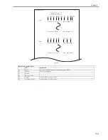
DTMF Signal Transmission Test
A press on '5' on the MODEM test menu selects the DTMF signal transmission test. In the test, the following DTMF signals from the modem are transmitted using
the telephone line terminal and the speaker. The number pressed on the keypad selects a specific DTMF signal.
MEMO:
The output level of individual signals is in keeping with the setting made in service mode.
Tonal/DTMF Signal Reception Test
A press on '6' on the keypad from the MODEM test menu selects the tonal signal/DTMF signal reception 0 test. In this signal, the tonal signal/DTMF signal received
from the telephone line terminal can be checked to find out if it was detected by the modem.
F-15-21
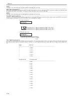
V.34 G3 Signal Transmission Test
A press on '8' on the keypad from the MODEM test menu selectes the V.34 G3 signal transmission test. The V.34 G3 signals below are sent from the modem using
the modular jack and the speaker by pressing the start key. The Baud rate can be changed with the keypad, and the Speed can be changed with the left/right arrow
key.
Keypad
Baud rate
0
3429baud
1
3200baud
2
3000baud
3
2800baud
4
2743baud
5
2400baud
Left/right arrow key
Transmission speed
2400bps
4800bps
7200bps
9600bps
<
12000bps
14400bps
16800bps
19200bps
21600bps
>
24000bps
26400bps
28800bps
31200bps
33600bps
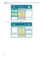
MODEM TEST
OFF OFF OFF
OFF OFF OFF
changes from '0' to '1' in response to detection of a signal of 462
25 Hz.
changes from '0' to '1' in response to detection of a signal of 1100
30 Hz.
changes from '0' to '1' in response to detection of a signal of 2100
25 Hz.
Tonal signal reception test
MODEM TEST
OFF OFF OFF 5
DTMF signal reception test
The received DTMF signals are indicated starting
from the right using the 2nd character of the display.
Summary of Contents for imageRunner 2022
Page 1: ...Aug 8 2007 Service Manual iR2030 2025 2022 2018 Series ...
Page 2: ......
Page 6: ......
Page 20: ...Contents ...
Page 21: ...Chapter 1 Introduction ...
Page 22: ......
Page 57: ...Chapter 1 1 33 ...
Page 60: ......
Page 61: ...T 1 11 ...
Page 64: ......
Page 65: ...T 1 12 ...
Page 68: ......
Page 69: ...Chapter 2 Installation ...
Page 70: ......
Page 72: ......
Page 125: ...Chapter 2 2 53 ...
Page 126: ......
Page 127: ...Chapter 3 Main Controller ...
Page 128: ......
Page 130: ......
Page 142: ......
Page 143: ...Chapter 4 Original Exposure System ...
Page 144: ......
Page 170: ......
Page 171: ...Chapter 5 Laser Exposure ...
Page 172: ......
Page 174: ......
Page 181: ...Chapter 6 Image Formation ...
Page 182: ......
Page 184: ......
Page 196: ......
Page 197: ...Chapter 7 Pickup Feeding System ...
Page 198: ......
Page 217: ...Chapter 8 Fixing System ...
Page 218: ......
Page 220: ......
Page 234: ......
Page 235: ...Chapter 9 External and Controls ...
Page 236: ......
Page 255: ...Chapter 10 RDS ...
Page 256: ......
Page 258: ......
Page 268: ......
Page 269: ...Chapter 11 Maintenance and Inspection ...
Page 270: ......
Page 272: ......
Page 275: ...Chapter 12 Standards and Adjustments ...
Page 276: ......
Page 278: ......
Page 281: ...Chapter 12 12 3 ...
Page 282: ......
Page 283: ...Chapter 13 Correcting Faulty Images ...
Page 284: ......
Page 286: ......
Page 299: ...F 13 11 F 13 12 1 2 3 4 5 6 7 8 9 10 11 12 13 14 15 16 17 ...
Page 300: ......
Page 301: ...Chapter 14 Self Diagnosis ...
Page 302: ......
Page 304: ......
Page 317: ...Chapter 15 Service Mode ...
Page 318: ......
Page 381: ...Chapter 16 Upgrading ...
Page 382: ......
Page 384: ......
Page 411: ...Chapter 17 Service Tools ...
Page 412: ......
Page 414: ......
Page 417: ...Aug 8 2007 ...
Page 418: ......


