


Chapter 4
4-22
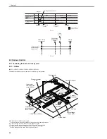
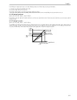
8) Remove the original sensor (vertical scan direction) [1].
- connector [2], 2 pcs
F-4-53
4.4.7.2 Removing the Original Sensor (Horizontal Scan
Direction)
0017-8505
iR2022i / iR2025 / iR2030 / iR2018 / iR2022 / iR2018i
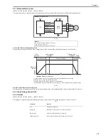
1) Open the copyboard cover (or ADF).
2) Remove the copyboard glass.
3) Detach the cover [1].
- Screw [2], 1 pcs
F-4-54
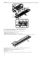
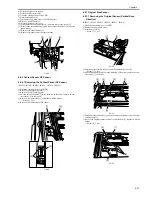
4) Disconnect the connector [1] from the reader controller PCB, and then re-
move the harness from the edge saddle [2].
5) Remove the original sensor [3] together with the mount.
- Screw [4], 2 pcs
F-4-55
6) Remove the harness from the edge saddle/clamp [1], and then disconnect
the connector.
7) Remove the original sensor [2].
F-4-56
4.4.8 Reader Heater (option)
4.4.8.1 Removing the Reader Heater (Right)
0017-8511
iR2022i / iR2025 / iR2030 / iR2018 / iR2022 / iR2018i
1) Open the copyboard cover (or ADF).
2) remove the copyboard glass.
3) Detach the heater cover [1].
- Screw [2], 1 pcs
F-4-57
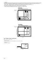
4) Remove the screw [1].
5) remove the reader heater (right) [2].
- wire saddle [3], 1 pcs
- connector [4], 1 pcs
F-4-58
4.4.8.2 Removing the Reader Heater (Left)
0017-8513
iR2022i / iR2025 / iR2030 / iR2018 / iR2022 / iR2018i
1) Open the copyboard cover (or ADF).
2) Detach the reader front cover.
3) Remove the glass retainer.
4) Remove the ADF reading glass.
[1]
[2]
[2]
[1]
[3]
[1]
[2]
[4]
[1]
[2]
[2]
[1]
[3]
[1]
[4]
[2]
Summary of Contents for imageRunner 2022
Page 1: ...Aug 8 2007 Service Manual iR2030 2025 2022 2018 Series ...
Page 2: ......
Page 6: ......
Page 20: ...Contents ...
Page 21: ...Chapter 1 Introduction ...
Page 22: ......
Page 57: ...Chapter 1 1 33 ...
Page 60: ......
Page 61: ...T 1 11 ...
Page 64: ......
Page 65: ...T 1 12 ...
Page 68: ......
Page 69: ...Chapter 2 Installation ...
Page 70: ......
Page 72: ......
Page 125: ...Chapter 2 2 53 ...
Page 126: ......
Page 127: ...Chapter 3 Main Controller ...
Page 128: ......
Page 130: ......
Page 142: ......
Page 143: ...Chapter 4 Original Exposure System ...
Page 144: ......
Page 170: ......
Page 171: ...Chapter 5 Laser Exposure ...
Page 172: ......
Page 174: ......
Page 181: ...Chapter 6 Image Formation ...
Page 182: ......
Page 184: ......
Page 196: ......
Page 197: ...Chapter 7 Pickup Feeding System ...
Page 198: ......
Page 217: ...Chapter 8 Fixing System ...
Page 218: ......
Page 220: ......
Page 234: ......
Page 235: ...Chapter 9 External and Controls ...
Page 236: ......
Page 255: ...Chapter 10 RDS ...
Page 256: ......
Page 258: ......
Page 268: ......
Page 269: ...Chapter 11 Maintenance and Inspection ...
Page 270: ......
Page 272: ......
Page 275: ...Chapter 12 Standards and Adjustments ...
Page 276: ......
Page 278: ......
Page 281: ...Chapter 12 12 3 ...
Page 282: ......
Page 283: ...Chapter 13 Correcting Faulty Images ...
Page 284: ......
Page 286: ......
Page 299: ...F 13 11 F 13 12 1 2 3 4 5 6 7 8 9 10 11 12 13 14 15 16 17 ...
Page 300: ......
Page 301: ...Chapter 14 Self Diagnosis ...
Page 302: ......
Page 304: ......
Page 317: ...Chapter 15 Service Mode ...
Page 318: ......
Page 381: ...Chapter 16 Upgrading ...
Page 382: ......
Page 384: ......
Page 411: ...Chapter 17 Service Tools ...
Page 412: ......
Page 414: ......
Page 417: ...Aug 8 2007 ...
Page 418: ......


