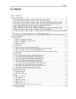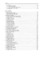
Contents
15.4.7
<No.010 Frequency of the pseudo CI signal> ................................................................................................... 15- 18
15.5
Setting of Numeric Parameter (NUMERIC Param.).............................................................................. 15- 18
15.5.1
Numerical Parameter Composition .................................................................................................................... 15- 18
15.5.2
<002: RTN transmission condition (1)><003: RTN transmission condition (2)><004: RTN transmission condition (3)>
15- 19
15.5.3
<005: NCC pause length (pre-ID code)> ........................................................................................................... 15- 19
15.5.4
<006: NCC pause length (post-ID code)> ......................................................................................................... 15- 19
15.5.5
<010: line connection identification length>....................................................................................................... 15- 19
15.5.6
<011: T.30 T1 timer (for reception)>.................................................................................................................. 15- 19
15.5.7
<013: T.30 EOL timer> ...................................................................................................................................... 15- 19
15.5.8
<016: time length to first response at time of fax/tel switchover> ...................................................................... 15- 20
15.5.9
<017: pseudo RBT signal pattern ON time length><018: pseudo RBT signal pattern OFF time length (short)><019:
pseudo RBT signal pattern OFF time length (long)> ............................................................................................... 15- 20
15.5.10
<020: pseudo CI signal pattern ON time length><021: pseudo CI signal pattern OFF time length (short)><022:
pseudo CI signal pattern OFF time length (long)>................................................................................................... 15- 20
15.5.11
<023: CNG detention level for fax/tel switchover> ........................................................................................... 15- 20
15.5.12
<024: pseudo RBT transmission level at time of fax/tel switchover> ............................................................... 15- 20
15.5.13
<025: Answering machine connection function signal detection time>............................................................ 15- 20
15.5.14
<027: V.21 low-speed flag preamble identification length> ............................................................................. 15- 20
15.5.15
<055: Acquisition period of environmental log data> ....................................................................................... 15- 20
15.5.16
<056 - 061: Count type select >....................................................................................................................... 15- 20
15.6
Setting of Scanner Functions (SCANNER)...........................................................................................15- 23
15.6.1
Setting of Bit Switch........................................................................................................................................... 15- 23
15.6.2
Numeric Parameter Functional configuration .................................................................................................... 15- 24
15.6.3
<024:CIS scan position during ADF scanning> ................................................................................................. 15- 25
15.6.4
<026:Distance from the standby position of CIS to the shading start point> ..................................................... 15- 25
15.6.5
<031Vertical scan start position adjustment> .................................................................................................... 15- 25
15.6.6
<032Horizontal scan start position adjustment>................................................................................................ 15- 25
15.6.7
<033Vertical scan magnification correction> ..................................................................................................... 15- 25
15.6.8
<035: - 036:Reader motor speed change>........................................................................................................ 15- 25
15.6.9
<041: Vertical scan start position adjustment (when scanning on a document fed from ADF)> ....................... 15- 26
15.6.10
<042: Horizontal scan start position adjustment (when scanning on a document fed from ADF)> ................. 15- 26
15.6.11
<043: Horizontal scan end position correction ((copy:scanning on ADF)> ...................................................... 15- 26
15.6.12
<044: Horizontal scan end position correction (superfine:scanning on ADF)> ................................................ 15- 26
15.6.13
<045: Horizontal scan end position correction (fine:scanning on ADF)> ......................................................... 15- 26
15.6.14
<046: Horizontal scan end position correction (standard:scanning on ADF)> ................................................. 15- 26
15.6.15
<047: Vertical scan magnification correction (when scanning on a document fed from ADF)>....................... 15- 26
15.6.16
<048: Horizontal scan magnification correction (when scanning on a document fed from ADF)> .................. 15- 26
15.6.17
<193: ADF special standard-sized paper: LGL misidentification-ready> ......................................................... 15- 26
15.6.18
<194: ADF special standard-sized paper: LTR misidentification-ready> ......................................................... 15- 26
15.6.19
<195: ADF special standard-sized paper: LTR_R misidentification-ready> .................................................... 15- 26
15.6.20
<196: Shading Target Value (Red)> ................................................................................................................ 15- 27
15.6.21
<197: Shading Target Value (Green)>............................................................................................................. 15- 27
15.6.22
<198: Shading Target Value (Blue)> ............................................................................................................... 15- 27
15.6.23
<213: XYZ correction value (X) of standard white plate> (if equipped with SEND functions)) ........................ 15- 27
15.6.24
<214: XYZ correction value (Y) of standard white plate> (if equipped with SEND functions).......................... 15- 27
15.6.25
<215: XYZ correction value (Z) of standard white plate> (if equipped with SEND functions) .......................... 15- 27
15.7
Setting of Printer Functions (PRINTER) ...............................................................................................15- 28
15.7.1
Service Soft Switch Settings (PRINTER)........................................................................................................... 15- 28
15.7.1.1
SSSW-SW05...................................................................................................................................................................... 15- 28
15.7.1.2
SSSW-SW14...................................................................................................................................................................... 15- 28
15.7.1.3
SSSW-SW15...................................................................................................................................................................... 15- 29
15.7.1.4
SSSW-SW18...................................................................................................................................................................... 15- 30
15.7.2
Numerin Parameter Settings (Numeric Prama.) ................................................................................................ 15- 31
15.7.2.1
List of Functions ................................................................................................................................................................. 15- 31
15.7.2.2
<031: Top registration adjustment (manual feed tray)> ..................................................................................................... 15- 31
15.7.2.3
<032: Top registration adjustment (cassette)>................................................................................................................... 15- 31
Summary of Contents for imageRunner 2022
Page 1: ...Aug 8 2007 Service Manual iR2030 2025 2022 2018 Series ...
Page 2: ......
Page 6: ......
Page 20: ...Contents ...
Page 21: ...Chapter 1 Introduction ...
Page 22: ......
Page 57: ...Chapter 1 1 33 ...
Page 60: ......
Page 61: ...T 1 11 ...
Page 64: ......
Page 65: ...T 1 12 ...
Page 68: ......
Page 69: ...Chapter 2 Installation ...
Page 70: ......
Page 72: ......
Page 125: ...Chapter 2 2 53 ...
Page 126: ......
Page 127: ...Chapter 3 Main Controller ...
Page 128: ......
Page 130: ......
Page 142: ......
Page 143: ...Chapter 4 Original Exposure System ...
Page 144: ......
Page 170: ......
Page 171: ...Chapter 5 Laser Exposure ...
Page 172: ......
Page 174: ......
Page 181: ...Chapter 6 Image Formation ...
Page 182: ......
Page 184: ......
Page 196: ......
Page 197: ...Chapter 7 Pickup Feeding System ...
Page 198: ......
Page 217: ...Chapter 8 Fixing System ...
Page 218: ......
Page 220: ......
Page 234: ......
Page 235: ...Chapter 9 External and Controls ...
Page 236: ......
Page 255: ...Chapter 10 RDS ...
Page 256: ......
Page 258: ......
Page 268: ......
Page 269: ...Chapter 11 Maintenance and Inspection ...
Page 270: ......
Page 272: ......
Page 275: ...Chapter 12 Standards and Adjustments ...
Page 276: ......
Page 278: ......
Page 281: ...Chapter 12 12 3 ...
Page 282: ......
Page 283: ...Chapter 13 Correcting Faulty Images ...
Page 284: ......
Page 286: ......
Page 299: ...F 13 11 F 13 12 1 2 3 4 5 6 7 8 9 10 11 12 13 14 15 16 17 ...
Page 300: ......
Page 301: ...Chapter 14 Self Diagnosis ...
Page 302: ......
Page 304: ......
Page 317: ...Chapter 15 Service Mode ...
Page 318: ......
Page 381: ...Chapter 16 Upgrading ...
Page 382: ......
Page 384: ......
Page 411: ...Chapter 17 Service Tools ...
Page 412: ......
Page 414: ......
Page 417: ...Aug 8 2007 ...
Page 418: ......

