


Chapter 4
4-2
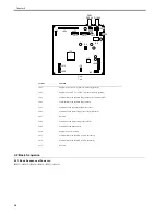
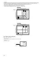
4.1.3 Major Components (iR2030i/iR2030/iR2025i/iR2025/iR2022i/iR2022)
0017-5568
iR2022i / iR2025 / iR2030 / iR2022
Major components of the original exposure system are as follows:
F-4-1
T-4-3
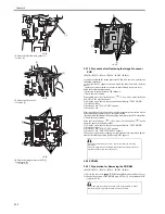
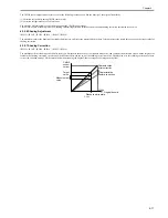
Carriage position
detection
Contact image sensor (CIS) HP sensor (SR401)
Magnification range
50% to 200%
Vertical scan direction:
Image processing is by image processor PCB
Horizontal scan direction:
BOOK mode:
Carriage movement speed change and image
processing by image processor PCB *1
ADF mode:
Original feed speed change and image processing by
image processor PCB *1
Lens
Rod lens array
CMOS sensor
Number of lines: 1
Number of pixels: Total 7488 (incl. 7176 effective pixels)
Maximum original scan width: 304 mm
CIS drive control
Drive control by reader motor (M401)
Original size detection
[1] BOOK mode: not used
[2] When ADF is used
Width:
Detection by original width sensor PCB in ADF
Length:
Detection by photo sensor in ADF
*1 The control method depends on the magnification. For more details, refer to "Magnification Change".
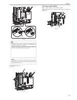
Component
No.
Function/Specification
[1]
Copyboard cover open/close
sensor (Rear: SR402)
SR402
Photo interrupter: Detects the copyboard cover open/
close status. Starts detecting the original size when the
copyboard cover angle is 30 deg.
[2]
Reader controller PCB
-
Controls drive of the reader unit and image processing.
[3]
Original sensor 3
SR406
Detects the original size (for all destinations).
[4]
Original sensor 4
SR407
Detects the original size (AB, INCH/AB).
[5]
Original sensor 5
SR408
Detects the original size (INCH/A)
[6]
Reader motor
M401
Pulse motor: Controls drive of the carriage.
Item
Function/Method
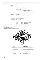
[6]
[4]
[5]
[3]
[9]
[8]
[2]
[1]
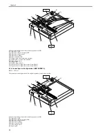
[12]
[7]
[7]
[11]
[10]
Summary of Contents for imageRunner 2022
Page 1: ...Aug 8 2007 Service Manual iR2030 2025 2022 2018 Series ...
Page 2: ......
Page 6: ......
Page 20: ...Contents ...
Page 21: ...Chapter 1 Introduction ...
Page 22: ......
Page 57: ...Chapter 1 1 33 ...
Page 60: ......
Page 61: ...T 1 11 ...
Page 64: ......
Page 65: ...T 1 12 ...
Page 68: ......
Page 69: ...Chapter 2 Installation ...
Page 70: ......
Page 72: ......
Page 125: ...Chapter 2 2 53 ...
Page 126: ......
Page 127: ...Chapter 3 Main Controller ...
Page 128: ......
Page 130: ......
Page 142: ......
Page 143: ...Chapter 4 Original Exposure System ...
Page 144: ......
Page 170: ......
Page 171: ...Chapter 5 Laser Exposure ...
Page 172: ......
Page 174: ......
Page 181: ...Chapter 6 Image Formation ...
Page 182: ......
Page 184: ......
Page 196: ......
Page 197: ...Chapter 7 Pickup Feeding System ...
Page 198: ......
Page 217: ...Chapter 8 Fixing System ...
Page 218: ......
Page 220: ......
Page 234: ......
Page 235: ...Chapter 9 External and Controls ...
Page 236: ......
Page 255: ...Chapter 10 RDS ...
Page 256: ......
Page 258: ......
Page 268: ......
Page 269: ...Chapter 11 Maintenance and Inspection ...
Page 270: ......
Page 272: ......
Page 275: ...Chapter 12 Standards and Adjustments ...
Page 276: ......
Page 278: ......
Page 281: ...Chapter 12 12 3 ...
Page 282: ......
Page 283: ...Chapter 13 Correcting Faulty Images ...
Page 284: ......
Page 286: ......
Page 299: ...F 13 11 F 13 12 1 2 3 4 5 6 7 8 9 10 11 12 13 14 15 16 17 ...
Page 300: ......
Page 301: ...Chapter 14 Self Diagnosis ...
Page 302: ......
Page 304: ......
Page 317: ...Chapter 15 Service Mode ...
Page 318: ......
Page 381: ...Chapter 16 Upgrading ...
Page 382: ......
Page 384: ......
Page 411: ...Chapter 17 Service Tools ...
Page 412: ......
Page 414: ......
Page 417: ...Aug 8 2007 ...
Page 418: ......


