


Chapter 10
10-2
(As for deletion of certificate, see 'CA certificate'.)
10.1.7 SOAP Communication Function
0017-6740
iR2022i / iR2025 / iR2030 / iR2018 / iR2022 / iR2018i
Following processings are enabled by use of SOAP communication (SSL client communication).
Server authentication is performed by use of CA*1 certificate issued by VeriSign.
In case the server certificate or CA certificate is expired, the device is not connected to UGW.
*1: CA stands for Certificate Authority, which are the institutions which issue electronic certificate used in e-commerce etc.
(1) Communication Test
- Perform the communication test
(2) Transmit all or a part of the following data based on the schedule information obtained from UGW.
- Counter details data
- Service mode counter
- Parts counter
- Mode counter
- ROM version
- Schedule information
- Application debug log
- Environment log (Device condition log)
(3) In case of detecting jam, or alert/service call error from the device, transmit the following to UGW.
- Transmission of alert code (transmit the counter information simultaneously)
Transmit an alert code in case of a change in the status of the device.
Main alert codes are toner LOW/OUT, jam, and door open.
At error recovery, transmit again the data that indicates the recovery.
- Transmission of jam log (transmit the counter information simultaneously)
- Transmission of service call (Error code) log (transmit the counter information simultaneously)
(4) Change of device schedule information
- Check whether there is a processing to execute.
- Update the schedule information.
- Return the result of the operation.
(5) Filtering reception from UGW
- Alert filtering
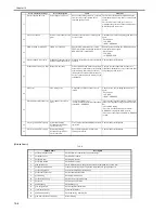
T-10-1
Transmission Detail List:
Transmission Detail / Process Detail
Transmission Timing
Remarks
Communication test
communicatonTest
Either at the time of execution of the service mode
of the device or upon a request from UGW with
'getOperationList'
Counter details data collection/transmission
postGlobalClickCount
Once every 16 hours.
The detailed counter data for each paper size
such as Total.
Service mode counter collection/transmission
postSeviceModeCounter
Once every 16 hours.
The counter data tied to the service mode
number. Mainly used for billing.
Mode counter collection/transmission
postModeCounter
Once every 16 hours.
The counter data by operation mode.
Parts counter collection/transmission
postPartsCounter
Once every 16 hours.
The counter data indicating the amount of
usage by part.
ROM version
postFirmwareInfo
Once every 7 days.
Schedule information transmission
postConfiguration
Once every 16 hours.
Debug log
postDebugLog
At the time that the log has been accumulated
5kbyte
The log data output by an application for
analyzing a malfunction.
Alert code
postAlert
At the time of change in the device condition
The data when a status change occurs.
Jam log
postJamLog
At the time of jam occurrence
Includes the jam code, date of occurrence,
total counter at occurrence, paper feeding slot,
and paper size.
Service call log
postServiceCallLog
At the time of service call occurrence
Includes the error code, error subcode, date of
occurrence, total counter at occurrence, paper
feeding slot, and paper size.
Summary of Contents for imageRunner 2022
Page 1: ...Aug 8 2007 Service Manual iR2030 2025 2022 2018 Series ...
Page 2: ......
Page 6: ......
Page 20: ...Contents ...
Page 21: ...Chapter 1 Introduction ...
Page 22: ......
Page 57: ...Chapter 1 1 33 ...
Page 60: ......
Page 61: ...T 1 11 ...
Page 64: ......
Page 65: ...T 1 12 ...
Page 68: ......
Page 69: ...Chapter 2 Installation ...
Page 70: ......
Page 72: ......
Page 125: ...Chapter 2 2 53 ...
Page 126: ......
Page 127: ...Chapter 3 Main Controller ...
Page 128: ......
Page 130: ......
Page 142: ......
Page 143: ...Chapter 4 Original Exposure System ...
Page 144: ......
Page 170: ......
Page 171: ...Chapter 5 Laser Exposure ...
Page 172: ......
Page 174: ......
Page 181: ...Chapter 6 Image Formation ...
Page 182: ......
Page 184: ......
Page 196: ......
Page 197: ...Chapter 7 Pickup Feeding System ...
Page 198: ......
Page 217: ...Chapter 8 Fixing System ...
Page 218: ......
Page 220: ......
Page 234: ......
Page 235: ...Chapter 9 External and Controls ...
Page 236: ......
Page 255: ...Chapter 10 RDS ...
Page 256: ......
Page 258: ......
Page 268: ......
Page 269: ...Chapter 11 Maintenance and Inspection ...
Page 270: ......
Page 272: ......
Page 275: ...Chapter 12 Standards and Adjustments ...
Page 276: ......
Page 278: ......
Page 281: ...Chapter 12 12 3 ...
Page 282: ......
Page 283: ...Chapter 13 Correcting Faulty Images ...
Page 284: ......
Page 286: ......
Page 299: ...F 13 11 F 13 12 1 2 3 4 5 6 7 8 9 10 11 12 13 14 15 16 17 ...
Page 300: ......
Page 301: ...Chapter 14 Self Diagnosis ...
Page 302: ......
Page 304: ......
Page 317: ...Chapter 15 Service Mode ...
Page 318: ......
Page 381: ...Chapter 16 Upgrading ...
Page 382: ......
Page 384: ......
Page 411: ...Chapter 17 Service Tools ...
Page 412: ......
Page 414: ......
Page 417: ...Aug 8 2007 ...
Page 418: ......


