


Chapter 7
7-9
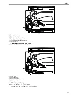
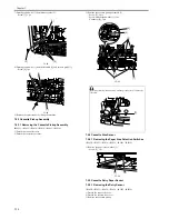
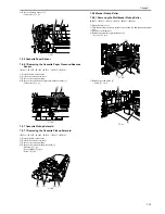
4) When the pickup roller rotates once, the toothless portion of the pickup roller drive gear comes to the position of the relay gear and consequently drive power of
the main motor is not transferred, stopping the rotation of pickup and feed rollers.
5) The picked up paper is fed to the registration roller through the vertical path roller.
F-7-13
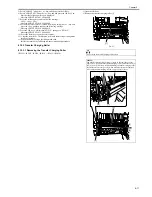
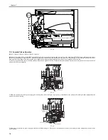
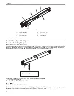
7.3.3 Cassette Paper Size Detection
0017-4388
iR2022i / iR2025 / iR2030 / iR2018 / iR2022 / iR2018i
The size of the paper in the cassette is detected by the DC controller PCB when the user changes the position of the cassette paper size lever. When the cassette is
inserted in the iR host machine, the paper size lever pushes the paper size switches provided in the iR host machine to allow the DC controller PCB to detect presence
of the cassette and the size of paper. Paper size switches are arranged as shown below. Paper sizes are determined by the combinations of the switches pushed by
the paper size lever.
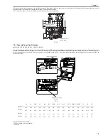
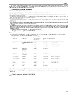
F-7-14
T-7-8
ON:The push switch is pushed.
OFF:The push switch is not pushed.
*:Not used.
A3
A4
A4R
A5
B4
B5
B5R
LGL
11x17
LTR
LTRR
STMT
U1
U2
U3
PSIZE1
ON
OFF
ON
OFF
OFF
ON
ON
OFF
ON
ON
ON
ON
OFF
OFF
OFF
PSIZE2
OFF
ON
OFF
ON
OFF
OFF
ON
ON
OFF
ON
ON
ON
ON
OFF
OFF
PSIZE3
OFF
OFF
ON
OFF
ON
OFF
OFF
ON
ON
OFF
ON
ON
ON
ON
OFF
PSIZE4
OFF
OFF
OFF
ON
OFF
ON
OFF
OFF
ON
ON
OFF
ON
ON
ON
ON
PSIZE4
PSIZE2
PSIZE1
PSIZE3
Summary of Contents for imageRunner 2022
Page 1: ...Aug 8 2007 Service Manual iR2030 2025 2022 2018 Series ...
Page 2: ......
Page 6: ......
Page 20: ...Contents ...
Page 21: ...Chapter 1 Introduction ...
Page 22: ......
Page 57: ...Chapter 1 1 33 ...
Page 60: ......
Page 61: ...T 1 11 ...
Page 64: ......
Page 65: ...T 1 12 ...
Page 68: ......
Page 69: ...Chapter 2 Installation ...
Page 70: ......
Page 72: ......
Page 125: ...Chapter 2 2 53 ...
Page 126: ......
Page 127: ...Chapter 3 Main Controller ...
Page 128: ......
Page 130: ......
Page 142: ......
Page 143: ...Chapter 4 Original Exposure System ...
Page 144: ......
Page 170: ......
Page 171: ...Chapter 5 Laser Exposure ...
Page 172: ......
Page 174: ......
Page 181: ...Chapter 6 Image Formation ...
Page 182: ......
Page 184: ......
Page 196: ......
Page 197: ...Chapter 7 Pickup Feeding System ...
Page 198: ......
Page 217: ...Chapter 8 Fixing System ...
Page 218: ......
Page 220: ......
Page 234: ......
Page 235: ...Chapter 9 External and Controls ...
Page 236: ......
Page 255: ...Chapter 10 RDS ...
Page 256: ......
Page 258: ......
Page 268: ......
Page 269: ...Chapter 11 Maintenance and Inspection ...
Page 270: ......
Page 272: ......
Page 275: ...Chapter 12 Standards and Adjustments ...
Page 276: ......
Page 278: ......
Page 281: ...Chapter 12 12 3 ...
Page 282: ......
Page 283: ...Chapter 13 Correcting Faulty Images ...
Page 284: ......
Page 286: ......
Page 299: ...F 13 11 F 13 12 1 2 3 4 5 6 7 8 9 10 11 12 13 14 15 16 17 ...
Page 300: ......
Page 301: ...Chapter 14 Self Diagnosis ...
Page 302: ......
Page 304: ......
Page 317: ...Chapter 15 Service Mode ...
Page 318: ......
Page 381: ...Chapter 16 Upgrading ...
Page 382: ......
Page 384: ......
Page 411: ...Chapter 17 Service Tools ...
Page 412: ......
Page 414: ......
Page 417: ...Aug 8 2007 ...
Page 418: ......


