


Chapter 6
6-6
6.5.2 Charging Mechanism
6.5.2.1 Primary Charging Bias Control
0017-4335
iR2022i / iR2025 / iR2030 / iR2018 / iR2022 / iR2018i
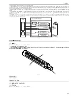
With the primary charging bias method, the drum is charged directly by the charging roller. In addition to a DC bias, an AC bias is applied to the primary charging
roller to stabilize charging. When the drum is charged, both AC and DC biases are applied. When the drum is discharged, only the AC bias is applied.
The ASIC on the DC controller PCB outputs the primary bias drive signal (/PRACFOT), primary AC bias ON/OFF signal (/PRACON), primary DC bias drive
signal (/PRDCFOT), and primary DC bias output level signal (/PRDCPWM) to apply the voltage generated by superimposing the primary AC bias over the primary
DC bias to the primary charging roller.
The primary AC bias is detected by the primary AC bias current detection circuit, and is fed back to the AC generator circuit via the comparison circuit.
The primary DC bias is detected by the primary DC bias current detection circuit, and is fed back to the DC generator circuit via the comparison circuit. Thus, this
machine controls the primary DC bias voltage. The primary DC bias voltage changes with the developing DC bias voltage according to the image density informa-
tion sent from the image processor PCB.
F-6-8
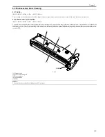
6.6 Developing Unit
6.6.1 Outline
0017-4351
iR2022i / iR2025 / iR2030 / iR2018 / iR2022 / iR2018i
Major components of the developing assembly are as follows:
F-6-9
[1] Developing Assembly
[2] Stirring plate
[3] Antenna rod
[4] Developing blade
[5] Developing cylinder
6.6.2 Developing Bias Control
0017-4353
iR2022i / iR2025 / iR2030 / iR2018 / iR2022 / iR2018i
JP3/JP4
/PRACON
/PRACFOT
/PRDCPWM
/PRDCFOT
To primary
charging roller
Primary bias circuit
ASIC
CPU
Primary DC bias voltage
detection circuit
DC generation circuit
AC generation circuit
Compariso
circuit
Primary AC bias current
detection circuit
Comparison
circuit
Superimposition
High-voltage power supply PCB
DC controller PCB
J214
J100
/PRACMONI
[1]
[2]
[3]
[4]
[5]
Summary of Contents for imageRunner 2022
Page 1: ...Aug 8 2007 Service Manual iR2030 2025 2022 2018 Series ...
Page 2: ......
Page 6: ......
Page 20: ...Contents ...
Page 21: ...Chapter 1 Introduction ...
Page 22: ......
Page 57: ...Chapter 1 1 33 ...
Page 60: ......
Page 61: ...T 1 11 ...
Page 64: ......
Page 65: ...T 1 12 ...
Page 68: ......
Page 69: ...Chapter 2 Installation ...
Page 70: ......
Page 72: ......
Page 125: ...Chapter 2 2 53 ...
Page 126: ......
Page 127: ...Chapter 3 Main Controller ...
Page 128: ......
Page 130: ......
Page 142: ......
Page 143: ...Chapter 4 Original Exposure System ...
Page 144: ......
Page 170: ......
Page 171: ...Chapter 5 Laser Exposure ...
Page 172: ......
Page 174: ......
Page 181: ...Chapter 6 Image Formation ...
Page 182: ......
Page 184: ......
Page 196: ......
Page 197: ...Chapter 7 Pickup Feeding System ...
Page 198: ......
Page 217: ...Chapter 8 Fixing System ...
Page 218: ......
Page 220: ......
Page 234: ......
Page 235: ...Chapter 9 External and Controls ...
Page 236: ......
Page 255: ...Chapter 10 RDS ...
Page 256: ......
Page 258: ......
Page 268: ......
Page 269: ...Chapter 11 Maintenance and Inspection ...
Page 270: ......
Page 272: ......
Page 275: ...Chapter 12 Standards and Adjustments ...
Page 276: ......
Page 278: ......
Page 281: ...Chapter 12 12 3 ...
Page 282: ......
Page 283: ...Chapter 13 Correcting Faulty Images ...
Page 284: ......
Page 286: ......
Page 299: ...F 13 11 F 13 12 1 2 3 4 5 6 7 8 9 10 11 12 13 14 15 16 17 ...
Page 300: ......
Page 301: ...Chapter 14 Self Diagnosis ...
Page 302: ......
Page 304: ......
Page 317: ...Chapter 15 Service Mode ...
Page 318: ......
Page 381: ...Chapter 16 Upgrading ...
Page 382: ......
Page 384: ......
Page 411: ...Chapter 17 Service Tools ...
Page 412: ......
Page 414: ......
Page 417: ...Aug 8 2007 ...
Page 418: ......


