


Chapter 15
15-53
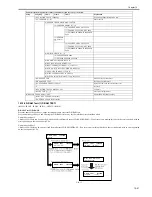
Press '1'or '2' on the keypad on the Modem test menu to select relay test mode. Use the keypad to operate the various relays of the NCU. '2' on the keypad is used
for 230V machine.
Numeric keypad key 1
The input key and relay are shown below:
F-15-19
Numeric keypad key 2
The input key and relay are shown below:
F-15-20
The touch panel (LCD) is turned on or off in relation to the transmission of the relay operation signal as is operated on the keypad; for this reason, you cannot use
the touch panel (LCD) to check a fault on a single relay.
Frequency Test
A press on '2' on the keypad from the MODEM test menu selects the frequency test.
In this test, signals of the following frequencies from the modem are transmitted using the telephone line terminal and the speaker. To select a different frequency,
use the keypad.
MEMO:
The frequency and the output level of individual frequencies are in keeping with the output level set in service mode.
G3 Signal Transmission Test
A press on '4' on the keypad from the MODEM test menu selects the G3 signal transmission test. In this test, the following G3 signals from the modem are trans-
mitted using the telephone line terminal and the speaker. To select a different transmission speed, use the keypad.
Keypad
Frequency
1
462Hz
2
1100Hz
3
1300Hz
4
1500Hz
5
1650Hz
6
1850Hz
7
2100Hz
Keypad
Transmission speed
0
300bps
1
2400bps
2
4800bps
3
7200bps
4
9600bps
5
TC7200bps
6
TC9600bps
7
12000bps
8
14400bps
RELAY TEST1 OFF OFF
OFF OFF OFF OFF
[1]
[2]
[3]
[4]
[5]
[6]
RELAY TEST2 OFF OFF
OFF OFF OFF OFF OFF
[1]
[2]
[3]
[4]
[5]
[6]
[7]
Summary of Contents for imageRunner 2022
Page 1: ...Aug 8 2007 Service Manual iR2030 2025 2022 2018 Series ...
Page 2: ......
Page 6: ......
Page 20: ...Contents ...
Page 21: ...Chapter 1 Introduction ...
Page 22: ......
Page 57: ...Chapter 1 1 33 ...
Page 60: ......
Page 61: ...T 1 11 ...
Page 64: ......
Page 65: ...T 1 12 ...
Page 68: ......
Page 69: ...Chapter 2 Installation ...
Page 70: ......
Page 72: ......
Page 125: ...Chapter 2 2 53 ...
Page 126: ......
Page 127: ...Chapter 3 Main Controller ...
Page 128: ......
Page 130: ......
Page 142: ......
Page 143: ...Chapter 4 Original Exposure System ...
Page 144: ......
Page 170: ......
Page 171: ...Chapter 5 Laser Exposure ...
Page 172: ......
Page 174: ......
Page 181: ...Chapter 6 Image Formation ...
Page 182: ......
Page 184: ......
Page 196: ......
Page 197: ...Chapter 7 Pickup Feeding System ...
Page 198: ......
Page 217: ...Chapter 8 Fixing System ...
Page 218: ......
Page 220: ......
Page 234: ......
Page 235: ...Chapter 9 External and Controls ...
Page 236: ......
Page 255: ...Chapter 10 RDS ...
Page 256: ......
Page 258: ......
Page 268: ......
Page 269: ...Chapter 11 Maintenance and Inspection ...
Page 270: ......
Page 272: ......
Page 275: ...Chapter 12 Standards and Adjustments ...
Page 276: ......
Page 278: ......
Page 281: ...Chapter 12 12 3 ...
Page 282: ......
Page 283: ...Chapter 13 Correcting Faulty Images ...
Page 284: ......
Page 286: ......
Page 299: ...F 13 11 F 13 12 1 2 3 4 5 6 7 8 9 10 11 12 13 14 15 16 17 ...
Page 300: ......
Page 301: ...Chapter 14 Self Diagnosis ...
Page 302: ......
Page 304: ......
Page 317: ...Chapter 15 Service Mode ...
Page 318: ......
Page 381: ...Chapter 16 Upgrading ...
Page 382: ......
Page 384: ......
Page 411: ...Chapter 17 Service Tools ...
Page 412: ......
Page 414: ......
Page 417: ...Aug 8 2007 ...
Page 418: ......


