


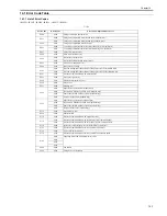


Chapter 14
14-3
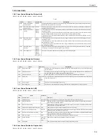
E197
0000
Printer engine communication error
Erroneous communication between the DC controller PCB and
image processor PCB was detected.
- Check the connectors of the DC controller PCB and image
processor PCB.
- Replace the DC controller PCB for normal connection.
- Replace the image processor PCB.
E261
0000
Zero-cross signal error
If failed to detect zero-cross signal cycle of the power supply
when initializing.
When the input of the zero-signal failed continuously for three
seconds while controlling the temperature adjustment.
- Replace the power supply PCB.
- Replace the DC controller PCB.
E716
0000
Erroneous communication with optional cassette
Disconnection of the optional cassette was detected after
power-on, detection of normal connection to the optional
cassette, and start of communication.
- Check the connectors of the optional cassette PCB and DC
controller PCB.
- Replace the optional cassette PCB for normal connection.
- Replace the DC controller PCB.
E719
0000
Erroneous communication with card reader (serial communication)
- Disconnection from the card reader has been detected since
communication started after confirmation of normal connection
to the card reader (after power-on).
- A serial communication error has occurred. (The serial
communication error cannot be recovered.)
- Check the connectors of the card reader and image processor PCB.
- Replace the card reader for normal connection.
- Replace the image processor PCB.
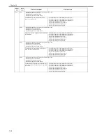
0002
Erroneous communication with coin vendor (serial communication)
- Disconnection from the coin vendor has been detected since
communication started after confirmation of normal connection
to the coin vendor (after power-on).
- A serial communication error has occurred. (The serial
communication error cannot be recovered.)
- Check the connection between the image processor PCB and serial
PCB.
- Check the connectors of the serial PCB and coin vendor for normal
connection.
- Replace the serial PCB.
- Check the coin vendor.
- Replace the image processor PCB.
E730
0000
Inside error of the image processor PCB (PDL system error)
The inside of the image processor PCB is faulty.
- Putting the switch on/off of the power supply.
- Replace the image processor PCB.
E733
0000
Erroneous communication between controller and printer
Cannot communicate with the printer at startup.
- Check the connectors of the DC controller PCB and image
processor PCB for normal connection.
- Check the power supply of the printer (Check whether initialization
is performed at startup).
- Replace the DC controller PCB or image processor PCB.
E736
0000
CCU communication error
The installed modem PCB is incompatible.
- Check the connectors of the image processor PCB and modem.
- Replace the modem PCB.
- Replace the image processor PCB.
E739
0000
Erroneous communication between controller and network board
The installed network board is incompatible.
- Check the connectors of the image processor PCB and LAN PCB
for normal connection.
- Replace the LAN PCB.
- Replace the image processor PCB.
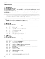
E744
Language file/boot ROM/USB memory error
0001
The language file version does not match Bootable.
Download a language file of the correct version.
0002
The language file is longer than the permitted size.
Download a language file of the correct version.
0003
The language file version does not match Bootable.
Download a language file of the correct version.
0004
Language file read error
Download a language file of the correct version.
E805
0000
Fan failure
The fan is faulty.
- Check the fan connector.
- Replace the fan.
- Replace the DC controller PCB.
Display
Code
Detail Code
Main Cause/Symptom
Countermeasure
Summary of Contents for imageRunner 2022
Page 1: ...Aug 8 2007 Service Manual iR2030 2025 2022 2018 Series ...
Page 2: ......
Page 6: ......
Page 20: ...Contents ...
Page 21: ...Chapter 1 Introduction ...
Page 22: ......
Page 57: ...Chapter 1 1 33 ...
Page 60: ......
Page 61: ...T 1 11 ...
Page 64: ......
Page 65: ...T 1 12 ...
Page 68: ......
Page 69: ...Chapter 2 Installation ...
Page 70: ......
Page 72: ......
Page 125: ...Chapter 2 2 53 ...
Page 126: ......
Page 127: ...Chapter 3 Main Controller ...
Page 128: ......
Page 130: ......
Page 142: ......
Page 143: ...Chapter 4 Original Exposure System ...
Page 144: ......
Page 170: ......
Page 171: ...Chapter 5 Laser Exposure ...
Page 172: ......
Page 174: ......
Page 181: ...Chapter 6 Image Formation ...
Page 182: ......
Page 184: ......
Page 196: ......
Page 197: ...Chapter 7 Pickup Feeding System ...
Page 198: ......
Page 217: ...Chapter 8 Fixing System ...
Page 218: ......
Page 220: ......
Page 234: ......
Page 235: ...Chapter 9 External and Controls ...
Page 236: ......
Page 255: ...Chapter 10 RDS ...
Page 256: ......
Page 258: ......
Page 268: ......
Page 269: ...Chapter 11 Maintenance and Inspection ...
Page 270: ......
Page 272: ......
Page 275: ...Chapter 12 Standards and Adjustments ...
Page 276: ......
Page 278: ......
Page 281: ...Chapter 12 12 3 ...
Page 282: ......
Page 283: ...Chapter 13 Correcting Faulty Images ...
Page 284: ......
Page 286: ......
Page 299: ...F 13 11 F 13 12 1 2 3 4 5 6 7 8 9 10 11 12 13 14 15 16 17 ...
Page 300: ......
Page 301: ...Chapter 14 Self Diagnosis ...
Page 302: ......
Page 304: ......
Page 317: ...Chapter 15 Service Mode ...
Page 318: ......
Page 381: ...Chapter 16 Upgrading ...
Page 382: ......
Page 384: ......
Page 411: ...Chapter 17 Service Tools ...
Page 412: ......
Page 414: ......
Page 417: ...Aug 8 2007 ...
Page 418: ......


