


Chapter 5
5-1
5.1 Construction
5.1.1 Overview
0017-2643
iR2022i / iR2025 / iR2030 / iR2018 / iR2022 / iR2018i
The laser scanner unit consists of a laser driver, scanner motor, and others. It is controlled by the signals from the DC controller PCB.
The laser driver operates the laser diode to emit light in response to the laser control signals and video signals from the DC controller PCB.
Laser beams are emitted, through a collimator lens and cylindrical lens, to the hexahedral mirror rotating at a constant speed.
Laser beam reflected by the hexahedral mirror focus on the photoconductor drum via the imaging lens and loop-back mirrors installed before the hexahedral mirror.
When the hexahedral mirror rotates at a constant speed, the photoconductor drum is scanned with laser beams at a constant speed.
When the photoconductor drum rotates at a constant speed and the photoconductor is scanned with laser beams at a constant speed, a latent image is formed on the
photoconductor drum.
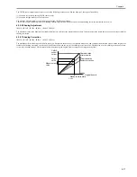
5.1.2 Specifications and Control Mechanism
0017-2646
iR2022i / iR2025 / iR2030 / iR2018 / iR2022 / iR2018i
T-5-1
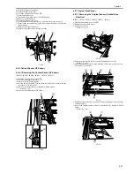
5.1.3 Main Components
0017-2647
iR2022i / iR2025 / iR2030 / iR2018 / iR2022 / iR2018i
F-5-1
T-5-2
Laser beam
Number of laser beams
2 beams
Scanner Motor
Type of motor
DC brushless motor
Rotation control
Constant speed rotaion control
Polygon Mirror
Number of facets
6 facets (40-mm dia.)
Control Mechanism
Synchronous control
Horizontal (main scan) synchronization
control
Light intensity control
Automatic photocurrent control (APC)
Others
Laser emission ON/OFF control
Laser scanner motor control
Laser shutter control
Name
Function
[1] Photoconductive drum
Receives laser beams to form a latent image.
[1]
[2]
[3]
[4]
[5]
[6]
[7]
Summary of Contents for imageRunner 2022
Page 1: ...Aug 8 2007 Service Manual iR2030 2025 2022 2018 Series ...
Page 2: ......
Page 6: ......
Page 20: ...Contents ...
Page 21: ...Chapter 1 Introduction ...
Page 22: ......
Page 57: ...Chapter 1 1 33 ...
Page 60: ......
Page 61: ...T 1 11 ...
Page 64: ......
Page 65: ...T 1 12 ...
Page 68: ......
Page 69: ...Chapter 2 Installation ...
Page 70: ......
Page 72: ......
Page 125: ...Chapter 2 2 53 ...
Page 126: ......
Page 127: ...Chapter 3 Main Controller ...
Page 128: ......
Page 130: ......
Page 142: ......
Page 143: ...Chapter 4 Original Exposure System ...
Page 144: ......
Page 170: ......
Page 171: ...Chapter 5 Laser Exposure ...
Page 172: ......
Page 174: ......
Page 181: ...Chapter 6 Image Formation ...
Page 182: ......
Page 184: ......
Page 196: ......
Page 197: ...Chapter 7 Pickup Feeding System ...
Page 198: ......
Page 217: ...Chapter 8 Fixing System ...
Page 218: ......
Page 220: ......
Page 234: ......
Page 235: ...Chapter 9 External and Controls ...
Page 236: ......
Page 255: ...Chapter 10 RDS ...
Page 256: ......
Page 258: ......
Page 268: ......
Page 269: ...Chapter 11 Maintenance and Inspection ...
Page 270: ......
Page 272: ......
Page 275: ...Chapter 12 Standards and Adjustments ...
Page 276: ......
Page 278: ......
Page 281: ...Chapter 12 12 3 ...
Page 282: ......
Page 283: ...Chapter 13 Correcting Faulty Images ...
Page 284: ......
Page 286: ......
Page 299: ...F 13 11 F 13 12 1 2 3 4 5 6 7 8 9 10 11 12 13 14 15 16 17 ...
Page 300: ......
Page 301: ...Chapter 14 Self Diagnosis ...
Page 302: ......
Page 304: ......
Page 317: ...Chapter 15 Service Mode ...
Page 318: ......
Page 381: ...Chapter 16 Upgrading ...
Page 382: ......
Page 384: ......
Page 411: ...Chapter 17 Service Tools ...
Page 412: ......
Page 414: ......
Page 417: ...Aug 8 2007 ...
Page 418: ......


