


Chapter 14
14-2
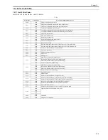
14.2 Error Code Details
14.2.1 Error Code Details
0017-6037
iR2022i / iR2025 / iR2030 / iR2018 / iR2022 / iR2018i
T-14-2
Display
Code
Detail Code
Main Cause/Symptom
Countermeasure
E000
0000
Startup error
The temperature detected by the main or sub thermistor does
not rise to the specified value during startup control.
- Check the fixing film connector.
- Replace the fixing film unit.
- Replace the DC controller PCB.
E001
0000
Abnormally high temperature (detected by main thermistor)
The main thermistor detected an abnormally high temperature
(240 deg C) during temperature control.
- Check the connector of the fixing film unit.
- Replace the fixing film unit.
- Replace the DC controller PCB.
0001
Abnormally high temperature (detected by sub thermistor)
The sub thermistor detected an abnormally high temperature
(295 deg C) during temperature control.
- Check the connector of the fixing film unit.
- Replace the fixing film unit.
- Replace the DC controller PCB.
E002
0000
Low temperature during temperature control.
The target temperature is not reached during temperature
control.
- Check the connector of the fixing film unit.
- Replace the fixing film unit.
- Replace the DC controller PCB.
E003
0000
Abnormally low temperature (detected by main thermistor)
After the temperature detected by the main thermistor has
reached the specified value, it does not reach the specified value
during initial rotation.
- Check the connector of the fixing film unit.
- Replace the fixing film unit.
- Replace the DC controller PCB.
0001
Abnormally low temperature (detected by sub thermistor)
After the temperature detected by the sub thermistor has
reached the specified value, it does not reach the specified value
during initial rotation.
- Check the connector of the fixing film unit.
- Replace the fixing film unit.
- Replace the DC controller PCB.
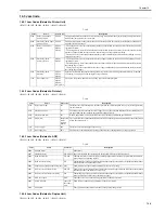
E007
0000
Fixing film sensor failure
The fixing film sensor is faulty.
- Check the connector of the fixing film sensor.
- Replace the fixing film sensor.
- Replace the DC controller PCB.
E010
0000
Main motor failure
The main motor is faulty.
- Check the connector of the main motor.
- Replace the main motor.
- Replace the DC controller PCB.
E019
0000
Waste toner full detection
The waste toner full state was detected.
Replace the drum unit.
0001
Waster toner full detection sensor is faulty.
The waste toner full state was detected continuously for five or
more seconds while the main motor was turning.
- Check the connector of the waster toner full sensor.
- Replace the waste toner full sensor.
- Replace the DC controller PCB.
E052
0000
Erroneous connection to duplex unit
Disconnection of the duplex unit was detected after power-on,
detection of normal connection to the duplex unit, and start of
communication.
- Check the connectors of the duplex unit and DC controller PCB.
- Replace the duplex controller PCB.
- Replace the DC controller PCB.
E100
0000
BD detection PCB failure
The BD detection PCB is faulty.
- Check the connector of the BD detection PCB.
- Replace the laser scanner unit.
- Replace the DC controller PCB.
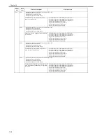
E196
0001
Image processor PCB failure
Error on writing and readout ROM of image processor PCB
(mainn ROM).
- Putting the switch on/off of the power supply.
- Replace the image processor PCB.
0002
Image processor PCB failure
Error on writing and readout ROM of image processor PCB
(option ROM).
- Putting the switch on/off of the power supply.
- Replace the image processor PCB.
Summary of Contents for imageRunner 2022
Page 1: ...Aug 8 2007 Service Manual iR2030 2025 2022 2018 Series ...
Page 2: ......
Page 6: ......
Page 20: ...Contents ...
Page 21: ...Chapter 1 Introduction ...
Page 22: ......
Page 57: ...Chapter 1 1 33 ...
Page 60: ......
Page 61: ...T 1 11 ...
Page 64: ......
Page 65: ...T 1 12 ...
Page 68: ......
Page 69: ...Chapter 2 Installation ...
Page 70: ......
Page 72: ......
Page 125: ...Chapter 2 2 53 ...
Page 126: ......
Page 127: ...Chapter 3 Main Controller ...
Page 128: ......
Page 130: ......
Page 142: ......
Page 143: ...Chapter 4 Original Exposure System ...
Page 144: ......
Page 170: ......
Page 171: ...Chapter 5 Laser Exposure ...
Page 172: ......
Page 174: ......
Page 181: ...Chapter 6 Image Formation ...
Page 182: ......
Page 184: ......
Page 196: ......
Page 197: ...Chapter 7 Pickup Feeding System ...
Page 198: ......
Page 217: ...Chapter 8 Fixing System ...
Page 218: ......
Page 220: ......
Page 234: ......
Page 235: ...Chapter 9 External and Controls ...
Page 236: ......
Page 255: ...Chapter 10 RDS ...
Page 256: ......
Page 258: ......
Page 268: ......
Page 269: ...Chapter 11 Maintenance and Inspection ...
Page 270: ......
Page 272: ......
Page 275: ...Chapter 12 Standards and Adjustments ...
Page 276: ......
Page 278: ......
Page 281: ...Chapter 12 12 3 ...
Page 282: ......
Page 283: ...Chapter 13 Correcting Faulty Images ...
Page 284: ......
Page 286: ......
Page 299: ...F 13 11 F 13 12 1 2 3 4 5 6 7 8 9 10 11 12 13 14 15 16 17 ...
Page 300: ......
Page 301: ...Chapter 14 Self Diagnosis ...
Page 302: ......
Page 304: ......
Page 317: ...Chapter 15 Service Mode ...
Page 318: ......
Page 381: ...Chapter 16 Upgrading ...
Page 382: ......
Page 384: ......
Page 411: ...Chapter 17 Service Tools ...
Page 412: ......
Page 414: ......
Page 417: ...Aug 8 2007 ...
Page 418: ......


