


Chapter 15
15-10
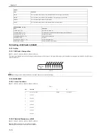
15.3 Setting of Bit Switch (SSSW)
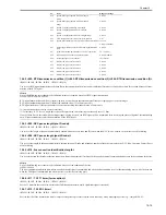
15.3.1 Outline
15.3.1.1 Bit Switch Composition
0017-6052
iR2022i / iR2025 / iR2030 / iR2018 / iR2022 / iR2018i
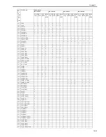
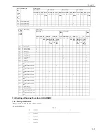
The items registered and set by each of these switches comprise 8-bit switches. The figure below shows which numbers are assigned to which bits. Each bit has a
value of either 0 or 1.
F-15-3
Do not change service data identified as "not used"; they are set as initial settings.
15.3.2 SSSW-SW01
15.3.2.1 List of Functions
0017-6053
iR2022i / iR2025 / iR2030 / iR2018 / iR2022 / iR2018i
T-15-1
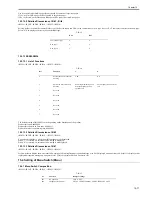
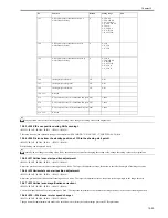
15.3.2.2 Detailed Discussions of Bit 0
0017-6054
iR2022i / iR2025 / iR2030 / iR2018 / iR2022 / iR2018i
Selects whether or not service error codes are output.
When output is selected, service error codes is report.
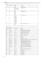
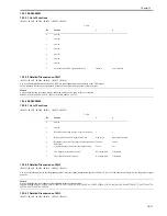
#ROM
Item
Function
MAIN
Use it to indicate the version of the ROM (SYSTEM) on the image processor PCB.
MAIN2
Use it to indicate the version of the ROM (BOOT) on the image processor PCB.
OPROM
Use it to indicate the version of option ROM.
ECONT
Use it to indicate the version of the ROM on the DC controller PCB.
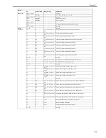
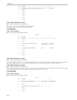
#TEST MODE [1] - [9]
Item
Function
(1) DRAM [1] - [2]
Data check in D-RAM
(2) SCAN TEST [1] - [8]
CS automatic correction and document scan position adjustment
(3) PRINT TEST [1] - [9]
Output of test prints
(4) MODEM TEST [1] - [9]
modem/NCU related tests
(5) AGING TEST
not used
(6) FACULTY TEST [1] - [9]
Various functional tests
(0) ROLLER CLEAN
Printer and ADF roller cleaning
Bit
Function
1
0
0
service error code
output
not output
1
not used
-
-
2
not used
-
-
3
not used
-
-
4
not used
-
-
5
not used
-
-
6
not used
-
-
7
not used
-
-
001
#SSSW
0
0
0
0
0
0
0
0
Bit 7 Bit 6 Bit 5 Bit 4 Bit 3 Bit 2 Bit 1 Bit 0
Summary of Contents for imageRunner 2022
Page 1: ...Aug 8 2007 Service Manual iR2030 2025 2022 2018 Series ...
Page 2: ......
Page 6: ......
Page 20: ...Contents ...
Page 21: ...Chapter 1 Introduction ...
Page 22: ......
Page 57: ...Chapter 1 1 33 ...
Page 60: ......
Page 61: ...T 1 11 ...
Page 64: ......
Page 65: ...T 1 12 ...
Page 68: ......
Page 69: ...Chapter 2 Installation ...
Page 70: ......
Page 72: ......
Page 125: ...Chapter 2 2 53 ...
Page 126: ......
Page 127: ...Chapter 3 Main Controller ...
Page 128: ......
Page 130: ......
Page 142: ......
Page 143: ...Chapter 4 Original Exposure System ...
Page 144: ......
Page 170: ......
Page 171: ...Chapter 5 Laser Exposure ...
Page 172: ......
Page 174: ......
Page 181: ...Chapter 6 Image Formation ...
Page 182: ......
Page 184: ......
Page 196: ......
Page 197: ...Chapter 7 Pickup Feeding System ...
Page 198: ......
Page 217: ...Chapter 8 Fixing System ...
Page 218: ......
Page 220: ......
Page 234: ......
Page 235: ...Chapter 9 External and Controls ...
Page 236: ......
Page 255: ...Chapter 10 RDS ...
Page 256: ......
Page 258: ......
Page 268: ......
Page 269: ...Chapter 11 Maintenance and Inspection ...
Page 270: ......
Page 272: ......
Page 275: ...Chapter 12 Standards and Adjustments ...
Page 276: ......
Page 278: ......
Page 281: ...Chapter 12 12 3 ...
Page 282: ......
Page 283: ...Chapter 13 Correcting Faulty Images ...
Page 284: ......
Page 286: ......
Page 299: ...F 13 11 F 13 12 1 2 3 4 5 6 7 8 9 10 11 12 13 14 15 16 17 ...
Page 300: ......
Page 301: ...Chapter 14 Self Diagnosis ...
Page 302: ......
Page 304: ......
Page 317: ...Chapter 15 Service Mode ...
Page 318: ......
Page 381: ...Chapter 16 Upgrading ...
Page 382: ......
Page 384: ......
Page 411: ...Chapter 17 Service Tools ...
Page 412: ......
Page 414: ......
Page 417: ...Aug 8 2007 ...
Page 418: ......


