


Chapter 10
10-6
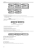
#CLEAR > ERDS-DAT
If necessary, install or delete CA Certificate and turn off/on the power.
(1)-3. Display the menu screen of e-RDS
Press the arrow key to move to the menu (#E-RDS) of e-RDS.
(2). Set E-RDS SWITCH to 1 in order to enable e-RDS.
(3). If necessary, enter URL of UGW in RGW-ADDRESS (The setting has normally been done).
(4). Enter the port number of UGW in RGW-PORT (normally the setting done).
(5). Select COM-TEST and press OK key to execute the test of communication with UGW.
(6). If the result is 'COM-TEST NG', correct the settings of RGW-ADDRESS/RGW-PORT and repeat COM-TEST until it becomes 'COM-TEST OK'. If necessary,
check the network settings of the device, the status of network connection and availability of the communication to UGW.
10.1.16 Troubleshooting
0017-6749
iR2022i / iR2025 / iR2030 / iR2018 / iR2022 / iR2018i
No.1
Q. Communication test fails.
A. Check the firmware version.
Check the network settings.
Check the results of communication test.
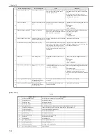
10.1.17 Error Message list
0017-6750
iR2022i / iR2025 / iR2030 / iR2018 / iR2022 / iR2018i
The followings are error information displayed on the 'Communication Error Log Detail Screen'.
(The term "server" used in this section refers to UGW.)
- When OK is pressed on the 'Communication Error Log Selection Screen' where a communication error log is displayed, the screen changes to the 'Communi-
cation Error Log Detail Screen'.
- When an error character string on the 'Communication Error Log Detail Screen' is so long that the entire message cannot be displayed on a screen at one time,
use the arrow keys to switch between screens. The amount of error information displayed on the 'Communication Error Log Detail Screen' is 128 characters at
maximum.
Error character strings from No.3 onward listed on the table below will be displayed in the following order.
[*][Error character string] : [Method name] [Server detail error]
Character strings bracketed in [] are replaced by the following.
[*]:
An '*' (asterisk) is added to the beginning of the error character string for errors occurred during communication test.
[Error character string]:
For No.1 and 2 of the [Error character string] below, only the error character strings are displayed. The rest of the error character strings are displayed in the
order described above.
T-10-3
Error Character Strings
Error Description
Cause
Measures
1
SUSPEND: Communication
test is not performed
e-RDS is ON but
Communication test is not
completed.
e-RDS is ON but e-RDS was activated
without performing Communication test.
(The device is rebooted.)
Perform and complete Communication test
(COM-TEST).
2
Event Registration is Failed.
Event registration failure
error
A processing (Event Registration) inside
the device has been failed.
Turn OFF and then ON the device.Otherwise
reinstall the device system software.
3
URL Scheme error(not https)
URL scheme specification
error
The URL header of the server registered is
not https.
Correct the header of the server URL to https.
Service Mode
> #E-RDS
> RGW-ADDRESS
4
Server connection error
Server connection error
Displayed when a TCP / IP
communication error occurs.
This error also occurs as a result of the
Proxy server dysfunction while the proxy
server is in use.
- Check the network connection.
- Check the port number for RGW-PORT.
- Check the server status.
- When the Proxy server is in use, check the
Proxy server address.
- When the Proxy server is in use, check the
status of the Proxy server address.
5
URL server specified is illegal Server-specified URL error
A different URL than the one specified by
the server has been registered.
Check with the server helpdesk.
Summary of Contents for imageRunner 2022
Page 1: ...Aug 8 2007 Service Manual iR2030 2025 2022 2018 Series ...
Page 2: ......
Page 6: ......
Page 20: ...Contents ...
Page 21: ...Chapter 1 Introduction ...
Page 22: ......
Page 57: ...Chapter 1 1 33 ...
Page 60: ......
Page 61: ...T 1 11 ...
Page 64: ......
Page 65: ...T 1 12 ...
Page 68: ......
Page 69: ...Chapter 2 Installation ...
Page 70: ......
Page 72: ......
Page 125: ...Chapter 2 2 53 ...
Page 126: ......
Page 127: ...Chapter 3 Main Controller ...
Page 128: ......
Page 130: ......
Page 142: ......
Page 143: ...Chapter 4 Original Exposure System ...
Page 144: ......
Page 170: ......
Page 171: ...Chapter 5 Laser Exposure ...
Page 172: ......
Page 174: ......
Page 181: ...Chapter 6 Image Formation ...
Page 182: ......
Page 184: ......
Page 196: ......
Page 197: ...Chapter 7 Pickup Feeding System ...
Page 198: ......
Page 217: ...Chapter 8 Fixing System ...
Page 218: ......
Page 220: ......
Page 234: ......
Page 235: ...Chapter 9 External and Controls ...
Page 236: ......
Page 255: ...Chapter 10 RDS ...
Page 256: ......
Page 258: ......
Page 268: ......
Page 269: ...Chapter 11 Maintenance and Inspection ...
Page 270: ......
Page 272: ......
Page 275: ...Chapter 12 Standards and Adjustments ...
Page 276: ......
Page 278: ......
Page 281: ...Chapter 12 12 3 ...
Page 282: ......
Page 283: ...Chapter 13 Correcting Faulty Images ...
Page 284: ......
Page 286: ......
Page 299: ...F 13 11 F 13 12 1 2 3 4 5 6 7 8 9 10 11 12 13 14 15 16 17 ...
Page 300: ......
Page 301: ...Chapter 14 Self Diagnosis ...
Page 302: ......
Page 304: ......
Page 317: ...Chapter 15 Service Mode ...
Page 318: ......
Page 381: ...Chapter 16 Upgrading ...
Page 382: ......
Page 384: ......
Page 411: ...Chapter 17 Service Tools ...
Page 412: ......
Page 414: ......
Page 417: ...Aug 8 2007 ...
Page 418: ......


