


Chapter 9
9-4
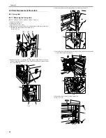
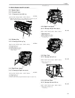
F-9-7
9.3.1.2 Rated Output of the Power Supply PCB
0017-9316
iR2022i / iR2025 / iR2030 / iR2018 / iR2022 / iR2018i
9.3.2 Protection Function
9.3.2.1 Protective Mechanisms
0017-5489
iR2022i / iR2025 / iR2030 / iR2018 / iR2022 / iR2018i
The power supply PCB is provided with an overcurrnet/overvoltage protection function to automatically cut off the output voltage when a trouble such as a short
circuit occurs on in the load.
When the overcurrnet/overvoltage protection function is activated, turn off the main power switch, solve the trouble with the load, and then turn on the main power
switch.
Further, the power supply circuit has two fuses which blow to stop power supply when an excessive current flows in the AC line.
Output
24V
5V
5VR
3.3V
3.3VR
Rated output voltage
24V
5.1V
5.1V
3.4V
3.4V
Output voltage tolerance
+10%, -5%
+3%, -4%
+3%, -4%
+3%, -3%
+3%, -3%
Rated output current
3.5A
1.0A
1.0A
2.0A
0.75A
Overcurrent protection trigger current
9.0A
4.0A
4.0A
4.0A
4.0A
Overvoltage protection trigger voltage
32.5V
8.0V
8.0V
5.5V
5.5V
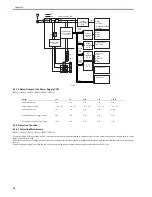
P1
NF
NF
Power supply PCB
: AC
: DC
F1
F2
SW1
TP1
H2
H1
Heater drive
circuit
RL1
SW2
SW3
Reader
controller
PCB
Low-voltage
power supply
circuit
+24V
+24VR
Option
power supply
PCB
Option
- Finisher
- Cassette feeding
module
+24Vop
DC
controller
PCB
Image
Processor
PCB
Control panel
FAX board
Motor
Sensor
DADF
Laser unit
Motor
Clutch
Solenoid
Fan
Sensor
HVT
PCB
+24V
+5VR
+3.3VR
+5V
+3.3V
+24VR
+24V
+5VR
+3.3VR
+24VR
+5VR
+3.3VR
Duplex unit
Inner2waytray
+24V
Summary of Contents for imageRunner 2022
Page 1: ...Aug 8 2007 Service Manual iR2030 2025 2022 2018 Series ...
Page 2: ......
Page 6: ......
Page 20: ...Contents ...
Page 21: ...Chapter 1 Introduction ...
Page 22: ......
Page 57: ...Chapter 1 1 33 ...
Page 60: ......
Page 61: ...T 1 11 ...
Page 64: ......
Page 65: ...T 1 12 ...
Page 68: ......
Page 69: ...Chapter 2 Installation ...
Page 70: ......
Page 72: ......
Page 125: ...Chapter 2 2 53 ...
Page 126: ......
Page 127: ...Chapter 3 Main Controller ...
Page 128: ......
Page 130: ......
Page 142: ......
Page 143: ...Chapter 4 Original Exposure System ...
Page 144: ......
Page 170: ......
Page 171: ...Chapter 5 Laser Exposure ...
Page 172: ......
Page 174: ......
Page 181: ...Chapter 6 Image Formation ...
Page 182: ......
Page 184: ......
Page 196: ......
Page 197: ...Chapter 7 Pickup Feeding System ...
Page 198: ......
Page 217: ...Chapter 8 Fixing System ...
Page 218: ......
Page 220: ......
Page 234: ......
Page 235: ...Chapter 9 External and Controls ...
Page 236: ......
Page 255: ...Chapter 10 RDS ...
Page 256: ......
Page 258: ......
Page 268: ......
Page 269: ...Chapter 11 Maintenance and Inspection ...
Page 270: ......
Page 272: ......
Page 275: ...Chapter 12 Standards and Adjustments ...
Page 276: ......
Page 278: ......
Page 281: ...Chapter 12 12 3 ...
Page 282: ......
Page 283: ...Chapter 13 Correcting Faulty Images ...
Page 284: ......
Page 286: ......
Page 299: ...F 13 11 F 13 12 1 2 3 4 5 6 7 8 9 10 11 12 13 14 15 16 17 ...
Page 300: ......
Page 301: ...Chapter 14 Self Diagnosis ...
Page 302: ......
Page 304: ......
Page 317: ...Chapter 15 Service Mode ...
Page 318: ......
Page 381: ...Chapter 16 Upgrading ...
Page 382: ......
Page 384: ......
Page 411: ...Chapter 17 Service Tools ...
Page 412: ......
Page 414: ......
Page 417: ...Aug 8 2007 ...
Page 418: ......


