


Chapter 15
15-52
15.19.5 Scan Test ((2) SCAN TEST)
0017-6197
iR2022i / iR2025 / iR2030 / iR2018 / iR2022 / iR2018i
Scan test ((2) SCAN TEST)
Press the numeric keypad key 2 on the test mode menu to select the CCD test.
Press numeric keypad keys 1, 3 and 4 during the CCD test to carry out the individual tests described below.
Numeric keypad key 1
Corrects the LED output of the contact sensor and sets its parameters automatically. (AGC adjustment)
Numeric keypad key 3
Adjusts the document scan position (only on models with the ADF feature installed). Adjusts the position of the contact sensor for scanning documents fed from
the ADF automatically.
Numeric keypad key 4
Detects trash at reader scan positions A/B/C.
Pos A: Reference read position
Pos B: About 0.5 mm inside of the roller from the reference position
Pos C: About 1.0 mm inside of the roller from the reference position
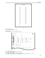
15.19.6 Print Test ((3) PRINT TEST)
0017-6198
iR2022i / iR2025 / iR2030 / iR2018 / iR2022 / iR2018i
Print test ((3) PRINT TEST)
Press the numeric keypad key 3 on the test mode menu to select the print test.
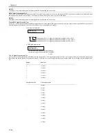
Press numeric keypad keys 2 and 4 during the print test to generate test patterns as described below. Two kinds of service test patterns are available. Other test
patterns are reserved for factory/development purposes.
Numeric keypad key 2
(2) BLACK: All-black output
Numeric keypad key 4
(4) ENDURANCE: Black belt output
To cancel test printing, press the stop key.
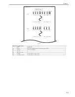
F-15-18
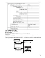
15.19.7 Modem Test ((4) MODEM TEST)
0017-6199
iR2022i / iR2025 / iR2030 / iR2018 / iR2022 / iR2018i
MODEM test((4) MODEM TEST)
These tests test modem and NCU transmission and reception. The modem tests check whether signals are sent correctly from the modem by comparing the sound
of the signals from the speaker with the sounds from a normal modem.
End this test by pressing the Stop key.
Relay Test
Keypad
Type
Description
1
Relay test
Use it to turn on/off a selected relay to execute a switch-over test
2
Frequency test
The modem sends tonal signals from the modular jack and the speaker.
4
G3 signal transmission test
The modem sends G3 signals from the modular jack and the speaker.
5
DTMF signal reception test
Use it to generate the DTMF signal coming from the modem using the
telephone line terminal and the speaker.
6
Tonal signal reception test
Use it to monitor a specific frequency and the DTMF signal received from
the telephone line terminal by causing them to be indicated on the LCD (i.e.,
the presence/absence as detected). The reception signal is generated by the
speaker.
8
V.34 G3 signal transmission test
The modem sends V.34 G3 signals from the modular jack and the speaker.
Use it to make sure that the print
pattern does not have white lines
or uneven image.
Use it to make sure that the print
pattern does not have contraction/
elongation of an image or dirt/black
line.s
Summary of Contents for imageRunner 2022
Page 1: ...Aug 8 2007 Service Manual iR2030 2025 2022 2018 Series ...
Page 2: ......
Page 6: ......
Page 20: ...Contents ...
Page 21: ...Chapter 1 Introduction ...
Page 22: ......
Page 57: ...Chapter 1 1 33 ...
Page 60: ......
Page 61: ...T 1 11 ...
Page 64: ......
Page 65: ...T 1 12 ...
Page 68: ......
Page 69: ...Chapter 2 Installation ...
Page 70: ......
Page 72: ......
Page 125: ...Chapter 2 2 53 ...
Page 126: ......
Page 127: ...Chapter 3 Main Controller ...
Page 128: ......
Page 130: ......
Page 142: ......
Page 143: ...Chapter 4 Original Exposure System ...
Page 144: ......
Page 170: ......
Page 171: ...Chapter 5 Laser Exposure ...
Page 172: ......
Page 174: ......
Page 181: ...Chapter 6 Image Formation ...
Page 182: ......
Page 184: ......
Page 196: ......
Page 197: ...Chapter 7 Pickup Feeding System ...
Page 198: ......
Page 217: ...Chapter 8 Fixing System ...
Page 218: ......
Page 220: ......
Page 234: ......
Page 235: ...Chapter 9 External and Controls ...
Page 236: ......
Page 255: ...Chapter 10 RDS ...
Page 256: ......
Page 258: ......
Page 268: ......
Page 269: ...Chapter 11 Maintenance and Inspection ...
Page 270: ......
Page 272: ......
Page 275: ...Chapter 12 Standards and Adjustments ...
Page 276: ......
Page 278: ......
Page 281: ...Chapter 12 12 3 ...
Page 282: ......
Page 283: ...Chapter 13 Correcting Faulty Images ...
Page 284: ......
Page 286: ......
Page 299: ...F 13 11 F 13 12 1 2 3 4 5 6 7 8 9 10 11 12 13 14 15 16 17 ...
Page 300: ......
Page 301: ...Chapter 14 Self Diagnosis ...
Page 302: ......
Page 304: ......
Page 317: ...Chapter 15 Service Mode ...
Page 318: ......
Page 381: ...Chapter 16 Upgrading ...
Page 382: ......
Page 384: ......
Page 411: ...Chapter 17 Service Tools ...
Page 412: ......
Page 414: ......
Page 417: ...Aug 8 2007 ...
Page 418: ......


