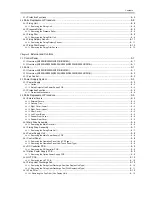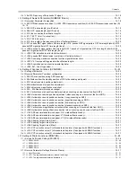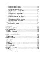
Contents
6.2
Image Formation Process ..........................................................................................................................6- 3
6.2.1
Image Formation Process ....................................................................................................................................... 6- 3
6.3
Basic Sequence..........................................................................................................................................6- 3
6.3.1
Basic Sequence of Operation.................................................................................................................................. 6- 3
6.4
Driving and Controlling the High-Voltage System.......................................................................................6- 5
6.4.1
Outline ..................................................................................................................................................................... 6- 5
6.5
Drum Unit ...................................................................................................................................................6- 5
6.5.1
Outline of the Drum Unit .......................................................................................................................................... 6- 5
6.5.1.1
Outline...................................................................................................................................................................................... 6- 5
6.5.2
Charging Mechanism............................................................................................................................................... 6- 6
6.5.2.1
Primary Charging Bias Control ................................................................................................................................................ 6- 6
6.6
Developing Unit ..........................................................................................................................................6- 6
6.6.1
Outline ..................................................................................................................................................................... 6- 6
6.6.2
Developing Bias Control .......................................................................................................................................... 6- 6
6.7
Toner Container..........................................................................................................................................6- 7
6.7.1
Outline ..................................................................................................................................................................... 6- 7
6.8
Transfer Unit ...............................................................................................................................................6- 7
6.8.1
Outline of the Transfer Unit ..................................................................................................................................... 6- 7
6.8.1.1
Outline...................................................................................................................................................................................... 6- 7
6.8.2
Controlling the Transfer Bias ................................................................................................................................... 6- 8
6.8.2.1
Transfer Roller Bias Control..................................................................................................................................................... 6- 8
6.8.3
Separation Mechanism ............................................................................................................................................ 6- 8
6.8.3.1
Static Eliminator Bias Control .................................................................................................................................................. 6- 8
6.9
Photosensitive Drum Cleaning ...................................................................................................................6- 9
6.9.1
Outline ..................................................................................................................................................................... 6- 9
6.9.2
Waste Toner Full Detection ..................................................................................................................................... 6- 9
6.10
Parts Replacement Procedure................................................................................................................6- 10
6.10.1
Drum Unit............................................................................................................................................................. 6- 10
6.10.1.1
Removing the Drum Unit...................................................................................................................................................... 6- 10
6.10.2
Developing Assembly .......................................................................................................................................... 6- 10
6.10.2.1
Removing the Developing Assembly ................................................................................................................................... 6- 10
6.10.2.2
Precautions about Installation of Developing Assembly ..................................................................................................... 6- 10
6.10.2.3
Procedure after Replacing the Developing Assembly .......................................................................................................... 6- 10
6.10.3
Transfer Charging Roller ..................................................................................................................................... 6- 11
6.10.3.1
Removing the Transfer Charging Roller............................................................................................................................... 6- 11
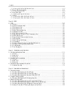
Chapter 7
Pickup/Feeding System
7.1
Construction ...............................................................................................................................................7- 1
7.1.1
Specifications/Configuration/Operation Methods .................................................................................................... 7- 1
7.1.2
Locations of Main Units ........................................................................................................................................... 7- 2
7.1.3
Roller Layout Drawing ............................................................................................................................................. 7- 2
7.1.4
Paper Path Drawing (Printer on its own) ................................................................................................................. 7- 3
7.1.5
Paper Path Drawing (Finisher-U2) .......................................................................................................................... 7- 3
7.1.6
Paper Path Drawing (Duplex Unit-B1/Finisher-U2) ................................................................................................. 7- 4
7.1.7
Paper Path Drawing (Duplex Unit-B1) ..................................................................................................................... 7- 4
7.1.8
Paper Path Drawing (Duplex-B1/Inner 2Way Tray-E2) ........................................................................................... 7- 4
7.1.9
Paper Path Drawing(Inner 2Way Tray-E2) .............................................................................................................. 7- 5
7.1.10
Sensor Layout Drawing ......................................................................................................................................... 7- 5
7.2
Detecting Jams ...........................................................................................................................................7- 6
7.2.1
Delay Jams.............................................................................................................................................................. 7- 6
7.2.1.1
Delay Jam in Pickup Assembly................................................................................................................................................ 7- 6
7.2.1.2
Delay Jam in Delivery Assembly (Paper Leading Edge Jam at First Delivery Sensor/Wound Paper Jam at Fixing Assembly) 7-
6
7.2.2
Stationary Jams ....................................................................................................................................................... 7- 7
7.2.2.1
Stationary Jam in Pickup Assembly ......................................................................................................................................... 7- 7
7.2.2.2
Stationary Jam in Delivery Assembly (Paper Trailing Edge Stationary Jam at First Delivery Sensor/Stationary Jam at First
Summary of Contents for imageRunner 2022
Page 1: ...Aug 8 2007 Service Manual iR2030 2025 2022 2018 Series ...
Page 2: ......
Page 6: ......
Page 20: ...Contents ...
Page 21: ...Chapter 1 Introduction ...
Page 22: ......
Page 57: ...Chapter 1 1 33 ...
Page 60: ......
Page 61: ...T 1 11 ...
Page 64: ......
Page 65: ...T 1 12 ...
Page 68: ......
Page 69: ...Chapter 2 Installation ...
Page 70: ......
Page 72: ......
Page 125: ...Chapter 2 2 53 ...
Page 126: ......
Page 127: ...Chapter 3 Main Controller ...
Page 128: ......
Page 130: ......
Page 142: ......
Page 143: ...Chapter 4 Original Exposure System ...
Page 144: ......
Page 170: ......
Page 171: ...Chapter 5 Laser Exposure ...
Page 172: ......
Page 174: ......
Page 181: ...Chapter 6 Image Formation ...
Page 182: ......
Page 184: ......
Page 196: ......
Page 197: ...Chapter 7 Pickup Feeding System ...
Page 198: ......
Page 217: ...Chapter 8 Fixing System ...
Page 218: ......
Page 220: ......
Page 234: ......
Page 235: ...Chapter 9 External and Controls ...
Page 236: ......
Page 255: ...Chapter 10 RDS ...
Page 256: ......
Page 258: ......
Page 268: ......
Page 269: ...Chapter 11 Maintenance and Inspection ...
Page 270: ......
Page 272: ......
Page 275: ...Chapter 12 Standards and Adjustments ...
Page 276: ......
Page 278: ......
Page 281: ...Chapter 12 12 3 ...
Page 282: ......
Page 283: ...Chapter 13 Correcting Faulty Images ...
Page 284: ......
Page 286: ......
Page 299: ...F 13 11 F 13 12 1 2 3 4 5 6 7 8 9 10 11 12 13 14 15 16 17 ...
Page 300: ......
Page 301: ...Chapter 14 Self Diagnosis ...
Page 302: ......
Page 304: ......
Page 317: ...Chapter 15 Service Mode ...
Page 318: ......
Page 381: ...Chapter 16 Upgrading ...
Page 382: ......
Page 384: ......
Page 411: ...Chapter 17 Service Tools ...
Page 412: ......
Page 414: ......
Page 417: ...Aug 8 2007 ...
Page 418: ......

