87
System Analysis
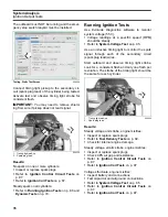
Ignition Output Tests
5
IMPORTANT:
If a running problem occurs at
about 1200 RPM, the outboard may be in
S.A.F.E.
Refer to
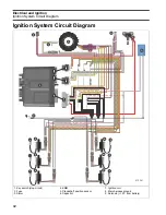
Ignition Control Circuit Tests
Use a digital multimeter to test the following:
•
System voltage supply to ignition coil.
•
Ignition control signal from
EMM
.
•
Engine harness resistance.
Disconnect ignition coil connector.
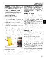
Supply voltage test:
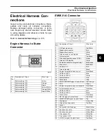
Use an appropriate adapter to connect the red
meter lead to pin 3 (white/red) of the engine har-
ness connector and the black lead to ground. With
EMM
ON, voltage should be approximately 30 V.
Control signal test:
Set meter to the Hz scale to check ignition control
signal.
Use an appropriate adapter to connect the red
meter lead to pin 2 (orange) of the engine harness
connector and the black lead to ground. Activate
diagnostics software
Static Ignition
test and
observe meter for consistent reading (approxi-
mately 2 Hz).
If control signal is present, connect black meter
lead to pin 1 (black) and repeat test to confirm
harness ground.
Harness resistance test:
If control signal is NOT present, calibrate multime-
ter to low ohms scale. Use appropriate adapters
on meter leads to avoid damaging harness con-
nectors.
With
EMM
OFF, remove the
EMM
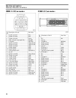
J1-B connector
and test the continuity of each ignition control cir-
cuit (orange). Check resistance between J1-B
connector and ignition coil connector. Refer to
engine wiring diagram. If circuits test good,
replace
EMM
.
Ignition Coil Tests
There are no simple ignition coil tests available.
Before replacing an ignition coil, be sure:
•
55 V is supplied to the white/red wire of the igni-
tion coil connector
•
A control signal is present on the orange wire of
the ignition coil connector. Refer to
•
The black wire of the ignition coil connector pro-
vides continuity to ground.
•
The secondary spark plug lead provides conti-
nuity.
If all of the above tests are good, and a cylinder
does not have spark, replace the ignition coil with
a known good coil.
Capacitor Test
IMPORTANT:
Make sure the capacitor is dis-
charged before testing. Make a momentary con-
nection between the two terminals to ground any
stored energy.
Remove capacitor from electrical harness.
Use an ohmmeter set on the high ohms scale to
test the capacitor. Connect the meter leads to the
capacitor terminals:
•
If the capacitor is working correctly, it will store
energy from the meter. The resistance reading
will increase until it goes to (nearly) infinity.
•
If the capacitor is shorted, the reading will
immediately show full continuity.
•
If there is an open circuit in the capacitor, the
meter will show no continuity.
If the resistance reading starts as a negative num-
ber, or the reading goes down in value, the capac-
itor already retains some stored energy. Ground
the capacitor and test again.
006609
Summary of Contents for EVINRUDE E-TEC BE225HGXABA
Page 163: ...Oiling System Oil Supply Diagrams 163 8 008208R Port Side View Starboard Side View ...
Page 165: ...Oiling System Oil Supply Diagrams 165 8 008432R Port Side View Starboard Side View ...
Page 167: ...Oiling System Oil Recirculation Diagrams 167 8 008207R Starboard View Port View ...
Page 251: ...Powerhead Powerhead Views 251 11 Powerhead Views Port Hose Routings 3 3 L models 007153 ...
Page 252: ...252 Powerhead Powerhead Views Starboard Hose Routings 3 3 L models 007154 ...
Page 253: ...Powerhead Powerhead Views 253 11 Port Hose Routings 3 4 L models 008503 ...
Page 254: ...254 Powerhead Powerhead Views Starboard Hose Routings 3 4 L models 008502 ...
Page 255: ...Powerhead Powerhead Views 255 11 Port 3 3 L models 008448 ...
Page 256: ...256 Powerhead Powerhead Views Starboard 3 3 L models 008449 ...
Page 257: ...Powerhead Powerhead Views 257 11 Port 3 4 L models 008441 ...
Page 258: ...258 Powerhead Powerhead Views Starboard 3 4 L models 008442 ...
Page 259: ...Powerhead Powerhead Views 259 11 Front 3 3 L models 008450 ...
Page 260: ...260 Powerhead Powerhead Views Front 3 4 L models 008439 ...
Page 261: ...Powerhead Powerhead Views 261 11 Rear 3 3 L models 007142 ...
Page 262: ...262 Powerhead Powerhead Views Rear 3 4 L models 008440 ...
Page 263: ...Powerhead Powerhead Views 263 11 Top 008438 ...
Page 264: ...264 Powerhead Powerhead Views Starboard ICON models 008504 ...
Page 269: ...Midsection Service Charts 269 12 Muffler 004117R ...
Page 320: ...S 322 ...


