Evinrude ICON Remote Control System
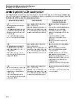
ICON System Fault Code Chart
219
10
110
Trim Switch Module Com-
munication Fault
Remote control cannot com-
municate with trim and tilt
switch panel (3, 4, or 5
engines only).
The fault message is sent
from the remote control to the
outboard’s
EMM
.
None
Trim and tilt switch panel harness
is damaged or not connected to
the remote control.
Trim and tilt switch panel harness
is damaged or not connected to
the switch panel.
Trim and tilt switch panel circuit
failure.
Remote control is programmed
with the wrong part number.
Trim Panel Check (Chart 12)
Remote Control Part Number
Check (Chart 4)
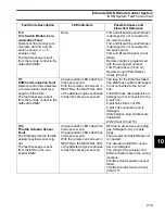
111
ESM
Communication Fault
Remote control has detected
a communication fault mes-
sage from the
ESM
.
The fault message is sent
from the remote control to the
outboard’s
EMM
.
All gear position LED’s flash five
times per second.
With the remote control lever in
NEUTRAL, the NEUTRAL LED
of the affected engine continues
to flash five times per second.
30A fuse for the
ESM
has failed.
The
ESM
buss cable is damaged
or not connected to the 6-port
hub.
The
ESM
buss cable extension is
damaged or not connected to the
6-port hub.
6-port hub LED is not ON
6-port hub connection port is
damaged.
ESM
instance plug numbers are
duplicated.
ESM
Check (Chart 16)
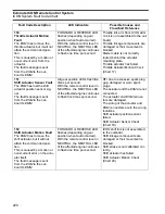
149
Throttle Actuator Sensor
Fault
The
ESM
has lost the throttle
actuator position sensor sig-
nal.
The fault message is sent
from the
ESM
to the out-
board’s
EMM
.
All gear position LED’s flash five
times per second.
All gear position LED’s flash five
times per second.
With the remote control lever in
NEUTRAL, the NEUTRAL LED
of the affected engine continues
to flash five times per second.
RFI due to excessive spark plug
gap, damaged or worn spark
plugs.
The actuator and the
ESM
are not
connected.
The actuator and
ESM
connec-
tors are damaged.
The wiring of the actuator and
ESM
connectors are in the wrong
locations.
Throttle actuator position sensor
failed.
Throttle Actuator Sensor Check
(Chart 17)
Fault Code Description
LED Indicators
Possible Causes and
Flowchart Reference
Summary of Contents for EVINRUDE E-TEC BE225HGXABA
Page 163: ...Oiling System Oil Supply Diagrams 163 8 008208R Port Side View Starboard Side View ...
Page 165: ...Oiling System Oil Supply Diagrams 165 8 008432R Port Side View Starboard Side View ...
Page 167: ...Oiling System Oil Recirculation Diagrams 167 8 008207R Starboard View Port View ...
Page 251: ...Powerhead Powerhead Views 251 11 Powerhead Views Port Hose Routings 3 3 L models 007153 ...
Page 252: ...252 Powerhead Powerhead Views Starboard Hose Routings 3 3 L models 007154 ...
Page 253: ...Powerhead Powerhead Views 253 11 Port Hose Routings 3 4 L models 008503 ...
Page 254: ...254 Powerhead Powerhead Views Starboard Hose Routings 3 4 L models 008502 ...
Page 255: ...Powerhead Powerhead Views 255 11 Port 3 3 L models 008448 ...
Page 256: ...256 Powerhead Powerhead Views Starboard 3 3 L models 008449 ...
Page 257: ...Powerhead Powerhead Views 257 11 Port 3 4 L models 008441 ...
Page 258: ...258 Powerhead Powerhead Views Starboard 3 4 L models 008442 ...
Page 259: ...Powerhead Powerhead Views 259 11 Front 3 3 L models 008450 ...
Page 260: ...260 Powerhead Powerhead Views Front 3 4 L models 008439 ...
Page 261: ...Powerhead Powerhead Views 261 11 Rear 3 3 L models 007142 ...
Page 262: ...262 Powerhead Powerhead Views Rear 3 4 L models 008440 ...
Page 263: ...Powerhead Powerhead Views 263 11 Top 008438 ...
Page 264: ...264 Powerhead Powerhead Views Starboard ICON models 008504 ...
Page 269: ...Midsection Service Charts 269 12 Muffler 004117R ...
Page 320: ...S 322 ...

