40
Routine Service
Lubrication
Inspection
Inspect the lubricant and the magnets on the
plugs for metal chips. The presence of metal
fuzz
can indicate normal wear of the gears, bearings,
or shafts within the gearcase. Metal
chips
can
indicate extensive internal damage.
Inspect the lubricant for water contamination.
Water can make the lubricant milky in appear-
ance. However, normal aeration can also cause
the same appearance.
To check for water contamination, put lubricant
into a glass container. Allow the oil to settle for a
minimum of one hour to determine if there is an
abnormal amount of water in the oil.
If water is present, refer to
Gearcase Leak Test
In the
Gearcase
service manual.
Overheated lubricant will have a black color and
burned odor.
Internal gearcase inspection is recommended
when lubricant is contaminated or shows signs of
failure.
Filling
Refer to the
on p. 18 for service frequency and rec-
ommended lubricants.
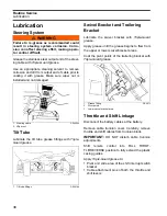
Secure the gearcase in a vertical position.
Remove the lubricant level plug and the lubricant
drain/fill plug.
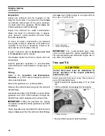
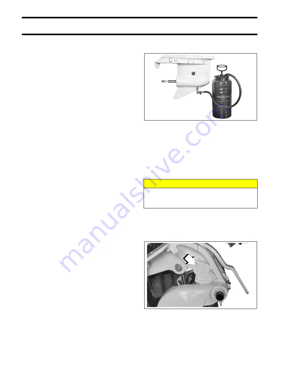
Use Gearcase Filler, P/N 501882, to slowly fill the
gearcase with
HPF PRO
lubricant through the
drain/fill hole until it appears at the oil level hole.
IMPORTANT:
Filling the gearcase too quickly
can cause air pockets and the gearcase may not fill
completely.
Clean plug seal area and install the lubricant level
plug and
new
seal, then the lubricant drain/fill plug
and
new
seal. Tighten plugs to a torque of 60 to
84 in. lbs. (7 to 9.5 N·m).
IMPORTANT:
The recommended gear lubri-
cants are formulated for marine applications. Do
not use automotive gear lubricants, engine oils, or
any other oil or grease.
Trim and Tilt
Check reservoir fluid level every three years or
every 300 operating hours.
•
System capacity is approximately 21 fl. oz. (620
ml).
•
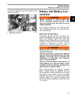
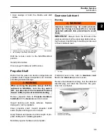
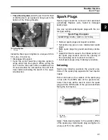
Tilt the outboard and engage the tilt support.
•
Remove filler cap and check fluid level.
1.
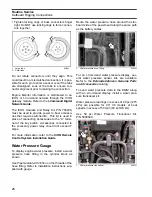
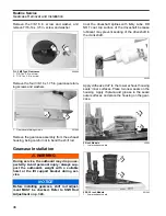
Lubricant level plug
2.
Lubricant drain/fill plug
002386
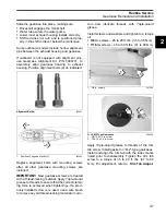
CAUTION
Correct fluid level must be maintained to
ensure operation of the impact protection
built into the unit.
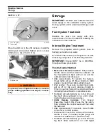
1.
Tilt support bracket
002279
1
Summary of Contents for EVINRUDE E-TEC BE225HGXABA
Page 163: ...Oiling System Oil Supply Diagrams 163 8 008208R Port Side View Starboard Side View ...
Page 165: ...Oiling System Oil Supply Diagrams 165 8 008432R Port Side View Starboard Side View ...
Page 167: ...Oiling System Oil Recirculation Diagrams 167 8 008207R Starboard View Port View ...
Page 251: ...Powerhead Powerhead Views 251 11 Powerhead Views Port Hose Routings 3 3 L models 007153 ...
Page 252: ...252 Powerhead Powerhead Views Starboard Hose Routings 3 3 L models 007154 ...
Page 253: ...Powerhead Powerhead Views 253 11 Port Hose Routings 3 4 L models 008503 ...
Page 254: ...254 Powerhead Powerhead Views Starboard Hose Routings 3 4 L models 008502 ...
Page 255: ...Powerhead Powerhead Views 255 11 Port 3 3 L models 008448 ...
Page 256: ...256 Powerhead Powerhead Views Starboard 3 3 L models 008449 ...
Page 257: ...Powerhead Powerhead Views 257 11 Port 3 4 L models 008441 ...
Page 258: ...258 Powerhead Powerhead Views Starboard 3 4 L models 008442 ...
Page 259: ...Powerhead Powerhead Views 259 11 Front 3 3 L models 008450 ...
Page 260: ...260 Powerhead Powerhead Views Front 3 4 L models 008439 ...
Page 261: ...Powerhead Powerhead Views 261 11 Rear 3 3 L models 007142 ...
Page 262: ...262 Powerhead Powerhead Views Rear 3 4 L models 008440 ...
Page 263: ...Powerhead Powerhead Views 263 11 Top 008438 ...
Page 264: ...264 Powerhead Powerhead Views Starboard ICON models 008504 ...
Page 269: ...Midsection Service Charts 269 12 Muffler 004117R ...
Page 320: ...S 322 ...

