36
Routine Service
Cooling System
Keep water inlet pressure between 20 to 40 psi
(140 to 275 kPa).
Flushing — Outboard Running
Place outboard in VERTICAL (DOWN) position in
a well ventilated area.
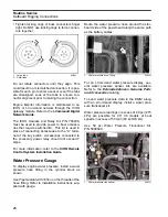
Remove plug and nozzle (overboard indicator)
from the flushing port.
Thread garden hose into flushing port.
Turn water supply on.
Run outboard at IDLE only until full operating tem-
perature is reached.
Reinstall plug and nozzle. Position the plug and
nozzle to allow the water stream to be seen from
the helm.
Leave the outboard in VERTICAL (DOWN) posi-
tion long enough for the powerhead to drain com-
pletely.
Reinstall propeller.
Flushing — Outboard Not Running
Outboard can be in VERTICAL (DOWN) or
TILTED (UP) position.
Remove plug and nozzle (overboard indicator)
from the flushing port.
Thread garden hose into flushing port.
Turn water supply ON.
Flush outboard for at least five minutes.
Turn off water supply and remove garden hose.
Reinstall plug and nozzle. Position the plug and
nozzle to allow the water stream to be seen from
the helm.
Leave the outboard in VERTICAL (DOWN) posi-
tion long enough for the powerhead to drain com-
pletely.
Running the Outboard Using a
Hose and Flushing Adapter
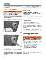
A flushing adapter may be used to provide cooling
water when running the outboard to:
•
Flush the engine
•
Run for an extended period of time, such as
when performing diagnostic work
•
Run the engine on a dynamometer
•
Prepare the outboard for storage.
IMPORTANT:
The outboard must be located in a
well ventilated area with appropriate ground drain-
age.
Keep water inlet pressure between 20 to 40 psi
(140 to 275 kPa).
WARNING
To prevent injury from contact with rotating
propeller, remove the propeller before run-
ning engine with a flushing adapter.
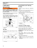
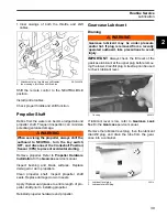
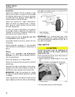
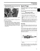
1.
004263
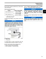
1.
004264
WARNING
To prevent injury from contact with rotating
propeller, remove the propeller before flush-
ing.
Summary of Contents for EVINRUDE E-TEC BE225HGXABA
Page 163: ...Oiling System Oil Supply Diagrams 163 8 008208R Port Side View Starboard Side View ...
Page 165: ...Oiling System Oil Supply Diagrams 165 8 008432R Port Side View Starboard Side View ...
Page 167: ...Oiling System Oil Recirculation Diagrams 167 8 008207R Starboard View Port View ...
Page 251: ...Powerhead Powerhead Views 251 11 Powerhead Views Port Hose Routings 3 3 L models 007153 ...
Page 252: ...252 Powerhead Powerhead Views Starboard Hose Routings 3 3 L models 007154 ...
Page 253: ...Powerhead Powerhead Views 253 11 Port Hose Routings 3 4 L models 008503 ...
Page 254: ...254 Powerhead Powerhead Views Starboard Hose Routings 3 4 L models 008502 ...
Page 255: ...Powerhead Powerhead Views 255 11 Port 3 3 L models 008448 ...
Page 256: ...256 Powerhead Powerhead Views Starboard 3 3 L models 008449 ...
Page 257: ...Powerhead Powerhead Views 257 11 Port 3 4 L models 008441 ...
Page 258: ...258 Powerhead Powerhead Views Starboard 3 4 L models 008442 ...
Page 259: ...Powerhead Powerhead Views 259 11 Front 3 3 L models 008450 ...
Page 260: ...260 Powerhead Powerhead Views Front 3 4 L models 008439 ...
Page 261: ...Powerhead Powerhead Views 261 11 Rear 3 3 L models 007142 ...
Page 262: ...262 Powerhead Powerhead Views Rear 3 4 L models 008440 ...
Page 263: ...Powerhead Powerhead Views 263 11 Top 008438 ...
Page 264: ...264 Powerhead Powerhead Views Starboard ICON models 008504 ...
Page 269: ...Midsection Service Charts 269 12 Muffler 004117R ...
Page 320: ...S 322 ...

