25
Routine Service
Outboard Rigging Connections
2
switch is on.
I-Command
Digital networks do not
use this connection.
Route the harnesses around the starboard side of
the powerhead along the same path as the battery
cables.
For an
I-Command
oil level display, an accessory
CANbus oil level sender must be installed in the
oil tank. Connect the sender to the
I-Command
network. Refer to the
I-Command
Digital Net-
work Guide
.
Use
Evinrude
Diagnostics
software to adjust net-
work settings in the
EMM
. From the
Settings
screen, select
Engine Options
.
ICON
Network Connections
If the outboard is equipped for an
Evinrude ICON
control system, connect the outboard to the net-
work as follows.
Refer to the
ICON
Remote Control System
Installation Guide
.
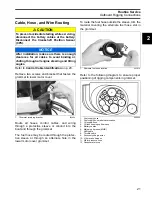
Connect the buss cable from the rear network hub
to the outboard’s network harness.
IMPORTANT:
Do not force connectors or locking
rings. Properly aligned connectors assemble easi-
ly.
Do not use
Electrical Grease
on
ICON
buss cable
connectors.
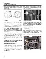
To assemble the connectors:
•
Use the large tabs and small tabs to carefully
align buss cable connectors.
•
Carefully align pins and sockets of connectors.
Do NOT force connectors together.
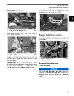
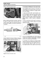
1.
I-Command
Ignition connector
2.
Trim/Tilt connector
3.
SystemCheck
connector (with seal)
4.
Network power supply connector (
Deutsch
style
networks)
006862
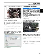
Engine Options Screen
008563
4
3
2
1
NOTICE
Do not connect boat accessories to the key
switch of an
ICON
system. Connecting acces-
sories to the key switch can cause low cur-
rent, resulting in erratic operation of the
remote control system.
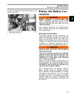
1.
ICON
network connector
008001
1
Summary of Contents for EVINRUDE E-TEC BE225HGXABA
Page 163: ...Oiling System Oil Supply Diagrams 163 8 008208R Port Side View Starboard Side View ...
Page 165: ...Oiling System Oil Supply Diagrams 165 8 008432R Port Side View Starboard Side View ...
Page 167: ...Oiling System Oil Recirculation Diagrams 167 8 008207R Starboard View Port View ...
Page 251: ...Powerhead Powerhead Views 251 11 Powerhead Views Port Hose Routings 3 3 L models 007153 ...
Page 252: ...252 Powerhead Powerhead Views Starboard Hose Routings 3 3 L models 007154 ...
Page 253: ...Powerhead Powerhead Views 253 11 Port Hose Routings 3 4 L models 008503 ...
Page 254: ...254 Powerhead Powerhead Views Starboard Hose Routings 3 4 L models 008502 ...
Page 255: ...Powerhead Powerhead Views 255 11 Port 3 3 L models 008448 ...
Page 256: ...256 Powerhead Powerhead Views Starboard 3 3 L models 008449 ...
Page 257: ...Powerhead Powerhead Views 257 11 Port 3 4 L models 008441 ...
Page 258: ...258 Powerhead Powerhead Views Starboard 3 4 L models 008442 ...
Page 259: ...Powerhead Powerhead Views 259 11 Front 3 3 L models 008450 ...
Page 260: ...260 Powerhead Powerhead Views Front 3 4 L models 008439 ...
Page 261: ...Powerhead Powerhead Views 261 11 Rear 3 3 L models 007142 ...
Page 262: ...262 Powerhead Powerhead Views Rear 3 4 L models 008440 ...
Page 263: ...Powerhead Powerhead Views 263 11 Top 008438 ...
Page 264: ...264 Powerhead Powerhead Views Starboard ICON models 008504 ...
Page 269: ...Midsection Service Charts 269 12 Muffler 004117R ...
Page 320: ...S 322 ...

