Electrical and Ignition
Flywheel and Stator Servicing
112
Flywheel and Stator Ser-
vicing
IMPORTANT:
Weak flywheel magnets can
cause low alternator output and affect outboard
performance. Weak flywheel magnets can also
cause low readings on ignition test equipment,
such as a peak-reading voltmeter, which might
cause unnecessary parts replacement.
An accurate test of alternator output can help
determine the flywheel’s condition. Refer to
Flywheel Removal
Use Flywheel Holder, P/N 771311, or equivalent,
and a 1 7/16 in. socket to remove flywheel nut.
Discard flywheel nut.
Assemble the following components from Univer-
sal Puller Set, P/N 378103:
•
Body, P/N 307636
•
Screw, P/N 307637
•
Handle, P/N 307638
•
Three screws P/N 309492
•
Three washers, P/N 307640
Apply
Moly Lube
grease to the threads of the
puller pressing screw, P/N 307637, and the center
hole of the crankshaft.
Place the puller on flywheel with body flat side up.
Attach the puller body with the three shoulder
screws and washers. Hold puller body with han-
dle, and tighten pressing screw until flywheel
releases. Turn the center screw and lift the fly-
wheel off of the crankshaft.
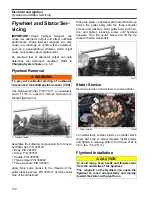
Stator Service
Remove six allen head screws to remove stator.
To install stator, position stator on cylinder block.
Apply
Nut Lock
to screw threads. Install screws
and tighten in crossing pattern to a torque of 24 to
36 in. lbs. (3 to 4 N·m).
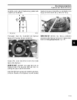
Flywheel Installation
WARNING
To prevent accidental starting of outboard,
disconnect crankshaft position sensor (CPS).
1.
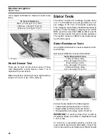
Flywheel holder
000774
1
000772
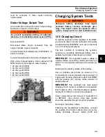
1.
Stator screws
006864
CAUTION
To avoid injury, keep hands and fingers clear
from the underside of the flywheel.
The magnets on the flywheel can cause the
flywheel to move unexpectedly and rapidly
toward the stator with great force.
1
1
Summary of Contents for EVINRUDE E-TEC BE225HGXABA
Page 163: ...Oiling System Oil Supply Diagrams 163 8 008208R Port Side View Starboard Side View ...
Page 165: ...Oiling System Oil Supply Diagrams 165 8 008432R Port Side View Starboard Side View ...
Page 167: ...Oiling System Oil Recirculation Diagrams 167 8 008207R Starboard View Port View ...
Page 251: ...Powerhead Powerhead Views 251 11 Powerhead Views Port Hose Routings 3 3 L models 007153 ...
Page 252: ...252 Powerhead Powerhead Views Starboard Hose Routings 3 3 L models 007154 ...
Page 253: ...Powerhead Powerhead Views 253 11 Port Hose Routings 3 4 L models 008503 ...
Page 254: ...254 Powerhead Powerhead Views Starboard Hose Routings 3 4 L models 008502 ...
Page 255: ...Powerhead Powerhead Views 255 11 Port 3 3 L models 008448 ...
Page 256: ...256 Powerhead Powerhead Views Starboard 3 3 L models 008449 ...
Page 257: ...Powerhead Powerhead Views 257 11 Port 3 4 L models 008441 ...
Page 258: ...258 Powerhead Powerhead Views Starboard 3 4 L models 008442 ...
Page 259: ...Powerhead Powerhead Views 259 11 Front 3 3 L models 008450 ...
Page 260: ...260 Powerhead Powerhead Views Front 3 4 L models 008439 ...
Page 261: ...Powerhead Powerhead Views 261 11 Rear 3 3 L models 007142 ...
Page 262: ...262 Powerhead Powerhead Views Rear 3 4 L models 008440 ...
Page 263: ...Powerhead Powerhead Views 263 11 Top 008438 ...
Page 264: ...264 Powerhead Powerhead Views Starboard ICON models 008504 ...
Page 269: ...Midsection Service Charts 269 12 Muffler 004117R ...
Page 320: ...S 322 ...

