45
Routine Service
Gearcase Removal and Installation
2
Testing Procedure – Continuity
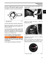
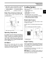
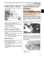
Connect ohmmeter leads between engine ground
and anode surface.
The meter should show little or no resistance. If
resistance is high, check the following:
•
Remove the anode and clean the area where
the anode is installed
•
Clean the mounting screws
•
Install the anode and test again.
Metallic Component Protection
Protect metal components on outboards from cor-
rosion. Use the following products to minimize
corrosion:
•
Anti-Corrosion Spray
provides a heavy, waxy
coating to protect components
•
“6 in 1” Multi-Purpose Lubricant
provides a thin
film of anti-corrosion protection.
Exterior Finishes
Maintain the outboard’s exterior finish to prevent
corrosion and reduce oxidation:
•
Use automotive wax to protect the outboard’s
exterior finish from oxidation
•
Clean regularly using clean water and mild
detergent soap
•
Touch-up damage to painted surfaces promptly.
•
Protect moving components with appropriate
lubricants.
Gearcase Removal and
Installation
Gearcase Removal
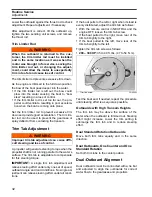
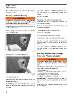
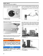
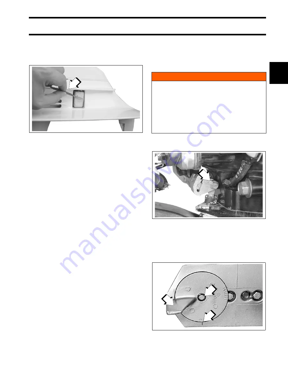
Remove pin and washer from shift rod lever to
release the lower shift rod.
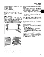
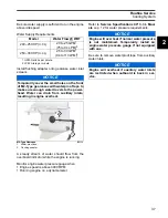
Note where the index mark on the gearcase aligns
with the index number of the adjustable trim tab so
the trim tab can be installed in the same position.
Remove the trim tab retaining screw and trim tab
from the gearcase.
1.
Meter lead to anode
000677
1
WARNING
Turn the key switch OFF, and disconnect the
Crankshaft Position Sensor (CPS), to prevent
accidental starting while servicing.
During service, the outboard may drop unex-
pectedly. Avoid personal injury; always sup-
port the outboard’s weight with a suitable
hoist or the tilt support bracket during ser-
vice.
1.
Shift rod pin
004241
1.
Index mark
2.
Trim tab
3.
Trim tab retaining screw
COA3663
1
2
3
1
Summary of Contents for EVINRUDE E-TEC BE225HGXABA
Page 163: ...Oiling System Oil Supply Diagrams 163 8 008208R Port Side View Starboard Side View ...
Page 165: ...Oiling System Oil Supply Diagrams 165 8 008432R Port Side View Starboard Side View ...
Page 167: ...Oiling System Oil Recirculation Diagrams 167 8 008207R Starboard View Port View ...
Page 251: ...Powerhead Powerhead Views 251 11 Powerhead Views Port Hose Routings 3 3 L models 007153 ...
Page 252: ...252 Powerhead Powerhead Views Starboard Hose Routings 3 3 L models 007154 ...
Page 253: ...Powerhead Powerhead Views 253 11 Port Hose Routings 3 4 L models 008503 ...
Page 254: ...254 Powerhead Powerhead Views Starboard Hose Routings 3 4 L models 008502 ...
Page 255: ...Powerhead Powerhead Views 255 11 Port 3 3 L models 008448 ...
Page 256: ...256 Powerhead Powerhead Views Starboard 3 3 L models 008449 ...
Page 257: ...Powerhead Powerhead Views 257 11 Port 3 4 L models 008441 ...
Page 258: ...258 Powerhead Powerhead Views Starboard 3 4 L models 008442 ...
Page 259: ...Powerhead Powerhead Views 259 11 Front 3 3 L models 008450 ...
Page 260: ...260 Powerhead Powerhead Views Front 3 4 L models 008439 ...
Page 261: ...Powerhead Powerhead Views 261 11 Rear 3 3 L models 007142 ...
Page 262: ...262 Powerhead Powerhead Views Rear 3 4 L models 008440 ...
Page 263: ...Powerhead Powerhead Views 263 11 Top 008438 ...
Page 264: ...264 Powerhead Powerhead Views Starboard ICON models 008504 ...
Page 269: ...Midsection Service Charts 269 12 Muffler 004117R ...
Page 320: ...S 322 ...

