137
Fuel System
Fuel System Requirements
7
Fuel System Require-
ments
Regulations and Guidelines
Vessel manufacturer, and/or installer of an EPA
certified outboard, must meet minimum specifica-
tions for boat fuel systems established by:
•
U.S. Environmental Protection Agency (EPA)
– 40 CFR 1045.112
– 40 CFR 1060
•
U.S. Coast Guard (USCG)
– 33 CFR 183
•
American Boat & Yacht Council (ABYC)
– Standard H-24
– Standard H-25.
Portable Fuel Tanks
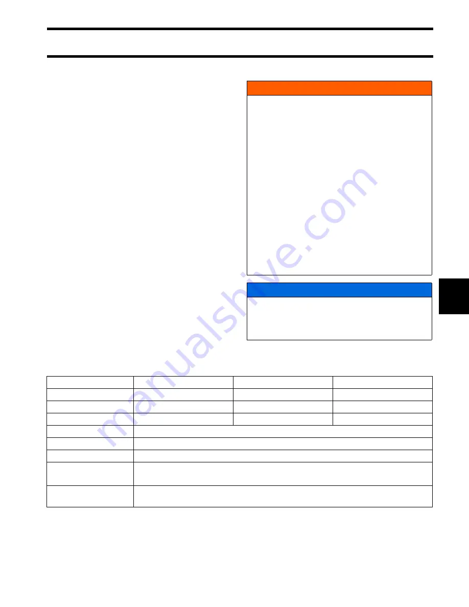
Fuel Flow Requirements
WARNING
If engine is equipped with a quick-disconnect
fuel hose, you MUST disconnect the fuel
hose from the engine and the fuel tank to pre-
vent fuel leaks:
•
Whenever the engine is NOT being used
•
Whenever the engine is being trailered
•
Whenever the engine is in storage.
NOTE: A small amount of fuel may be
released when the fuel connector is discon-
nected.
Store portable fuel tanks in well-ventilated
areas, away from heat sources and open
flames. Close the vent screw of the fuel tank
cap, if equipped, to prevent escape of fuel or
fuel vapors which could accidentally ignite.
Do not allow disconnected fuel hoses to leak
fuel.
NOTICE
Do not use portable fuel tanks for outboards
larger than 115 HP. Inadequate fuel flow to
high horsepower outboards can result in
serious powerhead damage.
15 – 30 HP
40 – 90 HP
115 – 300 HP
Fuel tank pickup tube
1/4 in. (6.4 mm) min. ID
5/16 in. (7.9 mm) min. ID
3/8 in. (9.5 mm) min. ID
Fuel fittings
5/32 in. (4.1 mm) min. ID
1/4 in. (6.4 mm) min. ID
9/32 in. (7.1 mm) min. ID
Fuel supply hoses
1/4 in. (6.4 mm) min. ID
3/8 in. (9.5 mm) min. ID
3/8 in. (9.5 mm) min. ID
All Models
Fuel tank pickup screen 100 mesh, 304 grade stainless steel wire, 0.0045 in. wire diameter, 1 in. (25 mm) long
Antisiphon valve
2.5 in. (63.5 mm) Hg maximum pressure drop at 20 gph (76 l/hr) flow
Remote fuel filter
0.4 in. Hg maximum pressure drop at 20 gph (76 l/hr) flow,
150 in.
2
(1290 cm
2
) of filter area
Maximum fuel pump lift
height
Fuel pump should not be located more than 30 in. (76.2 cm) above bottom of fuel tank
Summary of Contents for EVINRUDE E-TEC BE225HGXABA
Page 163: ...Oiling System Oil Supply Diagrams 163 8 008208R Port Side View Starboard Side View ...
Page 165: ...Oiling System Oil Supply Diagrams 165 8 008432R Port Side View Starboard Side View ...
Page 167: ...Oiling System Oil Recirculation Diagrams 167 8 008207R Starboard View Port View ...
Page 251: ...Powerhead Powerhead Views 251 11 Powerhead Views Port Hose Routings 3 3 L models 007153 ...
Page 252: ...252 Powerhead Powerhead Views Starboard Hose Routings 3 3 L models 007154 ...
Page 253: ...Powerhead Powerhead Views 253 11 Port Hose Routings 3 4 L models 008503 ...
Page 254: ...254 Powerhead Powerhead Views Starboard Hose Routings 3 4 L models 008502 ...
Page 255: ...Powerhead Powerhead Views 255 11 Port 3 3 L models 008448 ...
Page 256: ...256 Powerhead Powerhead Views Starboard 3 3 L models 008449 ...
Page 257: ...Powerhead Powerhead Views 257 11 Port 3 4 L models 008441 ...
Page 258: ...258 Powerhead Powerhead Views Starboard 3 4 L models 008442 ...
Page 259: ...Powerhead Powerhead Views 259 11 Front 3 3 L models 008450 ...
Page 260: ...260 Powerhead Powerhead Views Front 3 4 L models 008439 ...
Page 261: ...Powerhead Powerhead Views 261 11 Rear 3 3 L models 007142 ...
Page 262: ...262 Powerhead Powerhead Views Rear 3 4 L models 008440 ...
Page 263: ...Powerhead Powerhead Views 263 11 Top 008438 ...
Page 264: ...264 Powerhead Powerhead Views Starboard ICON models 008504 ...
Page 269: ...Midsection Service Charts 269 12 Muffler 004117R ...
Page 320: ...S 322 ...


