145
Fuel System
Fuel System Tests
7
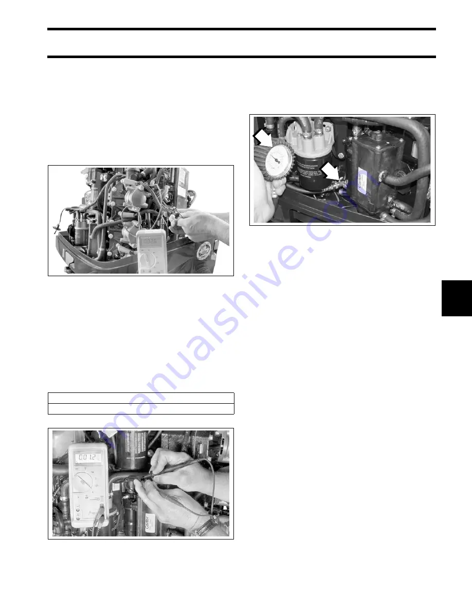
Use a digital multimeter with appropriate adapter
leads to measure resistance of the complete injec-
tor circuit, including injector and associated wiring.
Measure resistance between pin 1 (white/red) of
injector connector (connected) and the appropri-
ate pin location of
EMM
J1-B connector (discon-
nected). Refer to engine wiring diagram for
specific
EMM
J1-B connector pin location for the
injector circuit being tested (blue, purple or green).
Resistance should be the same as, or slightly
higher than, the injector alone.
Circulation Pump Resistance Test
Disconnect the battery cables at the battery.
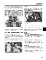
Use a digital multimeter with appropriate adapter
leads to measure the fuel pump circuit and coil
resistance.
Lift Pump Pressure Test
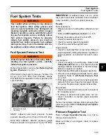
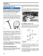
Install a 0 to 15 psi (0 to 103 kPa) Fuel Pressure
Gauge, P/N 5006397 or equivalent, to the lower
fuel pressure test fitting.
Prime the fuel system and check for leaks. START
outboard and run at idle speed. Hold gauge level
with inlet fitting and monitor gauge for pressure
reading.
Pressure should stabilize and gauge must not
indicate less than 4 psi (27 kPa).
Results:
Normal pressure
•
Perform the
Make sure no air leaks or restrictions exist in
the fuel supply hose or boat fuel system.
Low pressure
•
Check pulse hoses and fittings for restrictions.
•
Perform the
Make sure no air leaks or restrictions exist in
the fuel supply hose or boat fuel system.
•
Check fuel flow through fuel lift pump. Use fuel
primer bulb to force fuel through pump.
No pressure
•
Check pulse hoses and fittings restrictions.
•
Check fuel flow through fuel lift pump. Use fuel
primer or primer bulb to force fuel through
pump.
•
Momentarily prime or squeeze primer bulb to
check gauge operation.
•
Check pulse hose and fittings for restrictions.
004342
Fuel Pump Resistance
3
Ω
@ 77°F (25°C)
004217
1.
Fuel pressure gauge
2.
Test fitting
004587
1
2
Summary of Contents for EVINRUDE E-TEC BE225HGXABA
Page 163: ...Oiling System Oil Supply Diagrams 163 8 008208R Port Side View Starboard Side View ...
Page 165: ...Oiling System Oil Supply Diagrams 165 8 008432R Port Side View Starboard Side View ...
Page 167: ...Oiling System Oil Recirculation Diagrams 167 8 008207R Starboard View Port View ...
Page 251: ...Powerhead Powerhead Views 251 11 Powerhead Views Port Hose Routings 3 3 L models 007153 ...
Page 252: ...252 Powerhead Powerhead Views Starboard Hose Routings 3 3 L models 007154 ...
Page 253: ...Powerhead Powerhead Views 253 11 Port Hose Routings 3 4 L models 008503 ...
Page 254: ...254 Powerhead Powerhead Views Starboard Hose Routings 3 4 L models 008502 ...
Page 255: ...Powerhead Powerhead Views 255 11 Port 3 3 L models 008448 ...
Page 256: ...256 Powerhead Powerhead Views Starboard 3 3 L models 008449 ...
Page 257: ...Powerhead Powerhead Views 257 11 Port 3 4 L models 008441 ...
Page 258: ...258 Powerhead Powerhead Views Starboard 3 4 L models 008442 ...
Page 259: ...Powerhead Powerhead Views 259 11 Front 3 3 L models 008450 ...
Page 260: ...260 Powerhead Powerhead Views Front 3 4 L models 008439 ...
Page 261: ...Powerhead Powerhead Views 261 11 Rear 3 3 L models 007142 ...
Page 262: ...262 Powerhead Powerhead Views Rear 3 4 L models 008440 ...
Page 263: ...Powerhead Powerhead Views 263 11 Top 008438 ...
Page 264: ...264 Powerhead Powerhead Views Starboard ICON models 008504 ...
Page 269: ...Midsection Service Charts 269 12 Muffler 004117R ...
Page 320: ...S 322 ...

