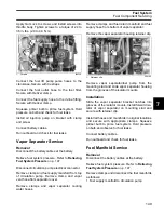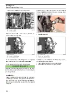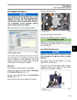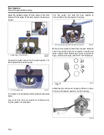
147
Fuel System
Fuel Component Servicing
7
Fuel Component Servic-
ing
Relieving Fuel System Pressure
IMPORTANT:
Minimize fuel system pressure pri-
or to disassembly. Temporarily restrict the fuel
supply hose from fuel tank with hose pincer. Re-
move propeller and disconnect circulation fuel
pump electrical connector. If outboard runs, start
and run at IDLE for 5 seconds and STOP outboard.
If outboard does NOT run, crank for 10 seconds.
Disconnect the battery cables at the battery.
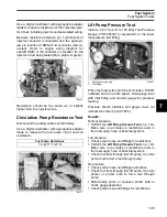
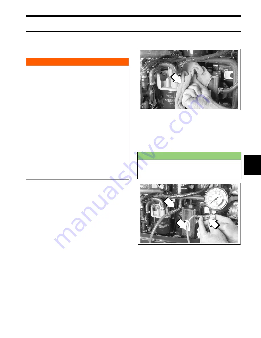
Wrap a shop towel completely around the pres-
sure test valve while connecting fitting from Fuel
Pressure Gauge, P/N 5007100, to top test fitting
of fuel pump/vapor separator assembly.
Insert venting hose of gauge into a suitable con-
tainer.
Slowly open gauge’s venting valve.
Clean up any spilled fuel with shop towels.
Fuel Filter Service
Removal
Disconnect the battery cables at the battery.
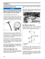
Use an appropriate filter wrench to turn the filter in
a counterclockwise direction. Remove the filter
carefully to prevent spilling the filter’s contents.
WARNING
Gasoline is extremely flammable and highly
explosive under certain conditions. Use cau-
tion when working on any part of the fuel sys-
tem.
Protect against hazardous fuel spray. Before
starting any fuel system service, carefully
relieve fuel system pressure. Refer to Reliev-
ing Fuel System Pressure.
Always disconnect the battery cables at the
battery before servicing the fuel system
unless instructed to do otherwise.
Always work in a well ventilated area and
wipe off any fuel spillage.
DO NOT smoke and make certain no open
flames or ignition sources exist.
After servicing the fuel system check for
leaks. Failure to check for fuel leakage could
allow a leak to go undetected, resulting in fire
or explosion.
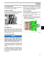
1.
Shop towel
004335
ENVIRONMENTAL NOTE
Dispose of fuel contaminated towels in an envi-
ronmentally responsible manner, or according to
local regulations.
1.
Test fitting
2.
Venting hose
3.
Venting valve
004334
1
1
2
3
Summary of Contents for EVINRUDE E-TEC BE225HGXABA
Page 163: ...Oiling System Oil Supply Diagrams 163 8 008208R Port Side View Starboard Side View ...
Page 165: ...Oiling System Oil Supply Diagrams 165 8 008432R Port Side View Starboard Side View ...
Page 167: ...Oiling System Oil Recirculation Diagrams 167 8 008207R Starboard View Port View ...
Page 251: ...Powerhead Powerhead Views 251 11 Powerhead Views Port Hose Routings 3 3 L models 007153 ...
Page 252: ...252 Powerhead Powerhead Views Starboard Hose Routings 3 3 L models 007154 ...
Page 253: ...Powerhead Powerhead Views 253 11 Port Hose Routings 3 4 L models 008503 ...
Page 254: ...254 Powerhead Powerhead Views Starboard Hose Routings 3 4 L models 008502 ...
Page 255: ...Powerhead Powerhead Views 255 11 Port 3 3 L models 008448 ...
Page 256: ...256 Powerhead Powerhead Views Starboard 3 3 L models 008449 ...
Page 257: ...Powerhead Powerhead Views 257 11 Port 3 4 L models 008441 ...
Page 258: ...258 Powerhead Powerhead Views Starboard 3 4 L models 008442 ...
Page 259: ...Powerhead Powerhead Views 259 11 Front 3 3 L models 008450 ...
Page 260: ...260 Powerhead Powerhead Views Front 3 4 L models 008439 ...
Page 261: ...Powerhead Powerhead Views 261 11 Rear 3 3 L models 007142 ...
Page 262: ...262 Powerhead Powerhead Views Rear 3 4 L models 008440 ...
Page 263: ...Powerhead Powerhead Views 263 11 Top 008438 ...
Page 264: ...264 Powerhead Powerhead Views Starboard ICON models 008504 ...
Page 269: ...Midsection Service Charts 269 12 Muffler 004117R ...
Page 320: ...S 322 ...

