28
Routine Service
Battery and Battery Connections
Battery Location
Proper installation will prevent battery movement
while underway.
•
Secure all batteries in protected locations
•
Place battery as close to the outboard as possi-
ble
•
Battery location must provide access for peri-
odic maintenance
•
Use battery mounting trays or battery boxes on
all battery installations
•
Connections and terminals must be covered
with an insulator
•
Battery connections must be clean and free
from corrosion
•
Read and understand the safety information
supplied with the battery before installation.
Battery Connections
Check battery connections frequently. Periodically
remove battery to clean and service connections.
•
Confirm that battery meets the minimum engine
requirements.
•
Connections must be clean and tight.
•
Observe all wiring connections prior to disas-
sembly.
Disconnecting the Battery
Disconnect battery negative (–) cable
first
and the
battery positive (+) cable last.
Clean all terminals, battery posts, and connectors
with a solution of baking soda and water. Use a
wire brush or battery terminal tool to remove cor-
rosion buildup. Rinse and clean all surfaces.
Connecting the Battery
IMPORTANT:
Connect the battery positive (+)
cable to the battery positive (+) post FIRST. Con-
nect the battery negative (–) cable to the battery
negative (–) post LAST.
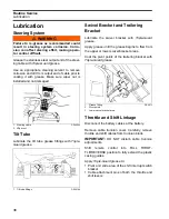
Install a star-washer on the threaded battery post.
Stack cables from the outboard, then cables from
accessories. Finish this connection with a hex nut.
Tighten all connections securely. Apply
Triple-
Guard
grease to prevent corrosion.
Outboard
Model
Battery Rating
200 H.O. –
300 HP
640 CCA (800 MCA) or
800 CCA (1000 MCA) below
32° F (0° C)
WARNING
Keep the battery connections clean, tight, and
insulated to prevent their shorting or arcing
and causing an explosion. If the battery
mounting system does not cover the connec-
tions, install protective covers. Check often to
see that connections stay clean and tight.
NOTICE
Do not use wing nuts to fasten ANY battery
cables. Wing nuts can loosen and cause elec-
trical system damage not covered under war-
ranty.
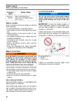
Marine Style Battery Post
1.
Starwasher
2.
Hex nut
3.
Terminal Insulator
DR5103
1
2
3
Summary of Contents for EVINRUDE E-TEC BE225HGXABA
Page 163: ...Oiling System Oil Supply Diagrams 163 8 008208R Port Side View Starboard Side View ...
Page 165: ...Oiling System Oil Supply Diagrams 165 8 008432R Port Side View Starboard Side View ...
Page 167: ...Oiling System Oil Recirculation Diagrams 167 8 008207R Starboard View Port View ...
Page 251: ...Powerhead Powerhead Views 251 11 Powerhead Views Port Hose Routings 3 3 L models 007153 ...
Page 252: ...252 Powerhead Powerhead Views Starboard Hose Routings 3 3 L models 007154 ...
Page 253: ...Powerhead Powerhead Views 253 11 Port Hose Routings 3 4 L models 008503 ...
Page 254: ...254 Powerhead Powerhead Views Starboard Hose Routings 3 4 L models 008502 ...
Page 255: ...Powerhead Powerhead Views 255 11 Port 3 3 L models 008448 ...
Page 256: ...256 Powerhead Powerhead Views Starboard 3 3 L models 008449 ...
Page 257: ...Powerhead Powerhead Views 257 11 Port 3 4 L models 008441 ...
Page 258: ...258 Powerhead Powerhead Views Starboard 3 4 L models 008442 ...
Page 259: ...Powerhead Powerhead Views 259 11 Front 3 3 L models 008450 ...
Page 260: ...260 Powerhead Powerhead Views Front 3 4 L models 008439 ...
Page 261: ...Powerhead Powerhead Views 261 11 Rear 3 3 L models 007142 ...
Page 262: ...262 Powerhead Powerhead Views Rear 3 4 L models 008440 ...
Page 263: ...Powerhead Powerhead Views 263 11 Top 008438 ...
Page 264: ...264 Powerhead Powerhead Views Starboard ICON models 008504 ...
Page 269: ...Midsection Service Charts 269 12 Muffler 004117R ...
Page 320: ...S 322 ...

