Oiling System
Oiling System Tests
178
Oiling System Tests
IMPORTANT:
Always perform visual inspections
to identify oiling system leaks. Make sure the oil
tank is filled and oil supply is not contaminated.
Oil Injection Pump Static Test
The
EMM
controls the pump by providing ground
through pin 23 (blue wire) of the J1-B connector
and pin 2 (blue wire) of the oil pump connector.
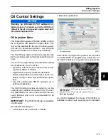
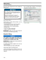
Use
Evinrude Diagnostics
software to activate the
Oil Injector
test. This test starts the
EMM
control
function for the oil injection pump.
IMPORTANT:
This test is operating the pump
with 30 V on the system voltage (55 V) circuit. The
start assist circuit (SAC) of the
EMM
converts bat-
tery voltage (12 V) to 30 V of system voltage. Bat-
tery must be fully charged and connections must
be clean and tight. Pump activation should be
carefully confirmed. Listen for an audible click from
the oil injection pump when it is activated.
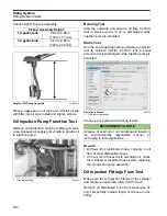
Use an inductive timing light to monitor current
flow through the ground circuit (blue wire) at the
oil pump connector (pin 2).
If the light flashes, the
EMM
and oil injection cir-
cuits are not at fault.
Refer to
Oil Injection Pump Voltage Tests
Oil Injection Pump Voltage Tests
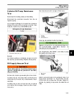
Use a digital multimeter calibrated to a scale that
reads 55 V (DC) to measure voltage between the
oil pump electrical connector and engine ground.
Connect negative meter lead to ground.
Use an appropriate test probe to connect positive
meter lead to pin 2 (blue wire) of oil injection pump
electrical connector.
Turn the key switch to the ON position. Observe
voltage at pin 2.
•
Voltage at pin 2 should be approximately 30 V.
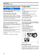
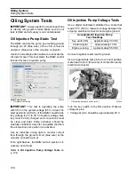
Static Tests Screen
1.
Oil injector test button
008579
1
Acceptable Oil Injection Pump
Test Readings
Key switch ON
approximately 30 VDC
Control signal
approximately 10 Hz
Engine running
approximately 55 VDC
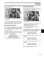
1.
Oil injection pump connector (pin 2)
004344
1
Summary of Contents for EVINRUDE E-TEC BE225HGXABA
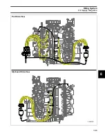
Page 163: ...Oiling System Oil Supply Diagrams 163 8 008208R Port Side View Starboard Side View ...
Page 165: ...Oiling System Oil Supply Diagrams 165 8 008432R Port Side View Starboard Side View ...
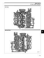
Page 167: ...Oiling System Oil Recirculation Diagrams 167 8 008207R Starboard View Port View ...
Page 251: ...Powerhead Powerhead Views 251 11 Powerhead Views Port Hose Routings 3 3 L models 007153 ...
Page 252: ...252 Powerhead Powerhead Views Starboard Hose Routings 3 3 L models 007154 ...
Page 253: ...Powerhead Powerhead Views 253 11 Port Hose Routings 3 4 L models 008503 ...
Page 254: ...254 Powerhead Powerhead Views Starboard Hose Routings 3 4 L models 008502 ...
Page 255: ...Powerhead Powerhead Views 255 11 Port 3 3 L models 008448 ...
Page 256: ...256 Powerhead Powerhead Views Starboard 3 3 L models 008449 ...
Page 257: ...Powerhead Powerhead Views 257 11 Port 3 4 L models 008441 ...
Page 258: ...258 Powerhead Powerhead Views Starboard 3 4 L models 008442 ...
Page 259: ...Powerhead Powerhead Views 259 11 Front 3 3 L models 008450 ...
Page 260: ...260 Powerhead Powerhead Views Front 3 4 L models 008439 ...
Page 261: ...Powerhead Powerhead Views 261 11 Rear 3 3 L models 007142 ...
Page 262: ...262 Powerhead Powerhead Views Rear 3 4 L models 008440 ...
Page 263: ...Powerhead Powerhead Views 263 11 Top 008438 ...
Page 264: ...264 Powerhead Powerhead Views Starboard ICON models 008504 ...
Page 269: ...Midsection Service Charts 269 12 Muffler 004117R ...
Page 320: ...S 322 ...

