Electrical and Ignition
Charging System Tests
100
Snap-On
model MT540D are examples of testers
available.
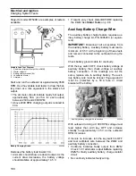
Start and run the outboard at approximately 3500
RPM. Use the variable load tester to draw the bat-
tery down at a rate equivalent to the stator’s full
output.
•
The ammeter should indicate nearly full output,
approximately 50 A (or 25 A for each output)
between 2000 and 4000 RPM.
•
Above 4000 RPM, charging output is reduced to
40 A.
Decrease the battery load toward 0 A.
•
Ammeter should show a reduced output. As the
current draw decreases, the battery voltage
should stabilize at approximately 14.5 V.
•
If results vary, check stator BEFORE replacing
the
EMM
. See
Auxiliary Battery Charge Wire
The auxiliary battery charge feature requires aux-
iliary battery charge kit, P/N 5006253 (or equiva-
lent).
IMPORTANT:
Disconnect all accessories from
the auxiliary battery. Auxiliary battery must read a
minimum of 8.5 V at the beginning of these tests
and remain connected to the outboard during the
tests.
Check battery ground cable for continuity.
With the key switch OFF, check battery voltage at
auxiliary battery, then check voltage at auxiliary
battery connection. If the readings are not the
same, replace wire to auxiliary battery. The auxil-
iary battery wire must be at least 10-gauge and it
must be protected by a 50 A fuse or circuit
breaker at the battery.
With outboard running at 1000 RPM, voltage must
read higher than with key OFF and increase
steadily to approximately 14.5 V as the outboard
RPM increases.
If there is no increase, turn the key switch to OFF
and test red/black wire between the
EMM
and
auxiliary battery connection.
•
Continuity indicates faulty output from
EMM
.
Check 12 V alternator output
before
replacing
EMM
for faulty auxiliary battery, charge isolator
circuit.
•
No continuity indicates faulty wiring.
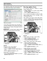
Variable Load Test Diagram
1.
Red wires (alternator output from
EMM
)
2.
Starter solenoid
3.
Battery cable terminal (B+)
4.
Variable load tester
5.
Ammeter
002077
Battery Charging Graph
004286
3
4
1
2
5
1.
Auxiliary battery charge wire connection
004329
1
Summary of Contents for EVINRUDE E-TEC BE225HGXABA
Page 163: ...Oiling System Oil Supply Diagrams 163 8 008208R Port Side View Starboard Side View ...
Page 165: ...Oiling System Oil Supply Diagrams 165 8 008432R Port Side View Starboard Side View ...
Page 167: ...Oiling System Oil Recirculation Diagrams 167 8 008207R Starboard View Port View ...
Page 251: ...Powerhead Powerhead Views 251 11 Powerhead Views Port Hose Routings 3 3 L models 007153 ...
Page 252: ...252 Powerhead Powerhead Views Starboard Hose Routings 3 3 L models 007154 ...
Page 253: ...Powerhead Powerhead Views 253 11 Port Hose Routings 3 4 L models 008503 ...
Page 254: ...254 Powerhead Powerhead Views Starboard Hose Routings 3 4 L models 008502 ...
Page 255: ...Powerhead Powerhead Views 255 11 Port 3 3 L models 008448 ...
Page 256: ...256 Powerhead Powerhead Views Starboard 3 3 L models 008449 ...
Page 257: ...Powerhead Powerhead Views 257 11 Port 3 4 L models 008441 ...
Page 258: ...258 Powerhead Powerhead Views Starboard 3 4 L models 008442 ...
Page 259: ...Powerhead Powerhead Views 259 11 Front 3 3 L models 008450 ...
Page 260: ...260 Powerhead Powerhead Views Front 3 4 L models 008439 ...
Page 261: ...Powerhead Powerhead Views 261 11 Rear 3 3 L models 007142 ...
Page 262: ...262 Powerhead Powerhead Views Rear 3 4 L models 008440 ...
Page 263: ...Powerhead Powerhead Views 263 11 Top 008438 ...
Page 264: ...264 Powerhead Powerhead Views Starboard ICON models 008504 ...
Page 269: ...Midsection Service Charts 269 12 Muffler 004117R ...
Page 320: ...S 322 ...

