background image

5-6

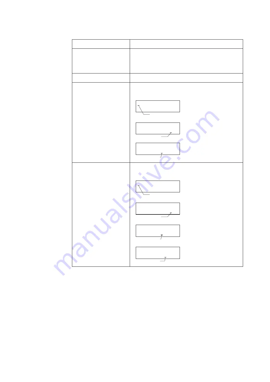
This section describes keys on the data setting device.

Name

Description

MODE key


„

Enters OPERATOR'S MODE.


„

When parameters and configured data have been changed 

in ENGINEERING MODE or MAINTENANCE MODE, 

press this key to save the data.

Right shift key


„

Moves the cursor to the right.

Decrement key


„

Changes the parameter at a cursor position.


„

Displays the previous screen.

If the key is pressed, when the 

cursor is placed at the upper 

left end (*, #, >), the screen 

will change 
If the key is pressed, when the 

cursor is placed at a number, 

the number is decremented.

If the cursor is placed at a 

decimal point, the decimal 

point moves rightward. 

*  OPERATOR'S

MODE

Cursor

*  DAMPING

001.0 S

Cursor

#                   1.0000 m/s
SPAN          07. 069 m

3

/h

Cursor

Increment key


„

Changes the parameter at a cursor position.


„

Displays the following screen.

If the key is pressed, when the 

cursor is placed at the upper 

left end (*, #, >), the screen 

will change.  
If the key is pressed, when the 

cursor is placed at a number, 

the number is incremented. 

If the key is pressed, when the 

cursor is placed at a decimal 

point, the decimal point 

moves to the left.  
If the cursor is placed over 

READY, pressing the key 

starts operation. 

*  OPERATOR'S

MODE

Cursor

*  DAMPING

001.0 S

Cursor

#                   1.0000 m/s
SPAN          07. 069 m

3

/h

Cursor

*  AUTO  ZERO

READY

Cursor

Summary of Contents for MagneW Two-wire PLUS+ MTG15A

Page 1: ...CM2 MTG400 2001 MagneWTM Two wire PLUS Two wire Electromagnetic Flowmeter TIIS KCs Explosion protected Apparatus Model MTG15A User s Manual...

Page 2: ...s for a particular purpose and makes no express warranty except as may be stated in its written agreement with and for its customer In no event shall Azbil Corporation be liable to anyone for any indi...

Page 3: ...ATT To use this product correctly and safely always observe the following precautions We are not responsible for damage or injury caused by the use of the product in violation of these precautions Han...

Page 4: ...specifications carefully and make sure to wire correctly Incorrect wiring can cause device damage or malfunction Supply electric power correctly according to the specifications Supplying power that d...

Page 5: ...ing the data setting device 5 1 5 1 Startup 5 2 5 2 Functions of the data setting device 5 5 5 2 1 Data setting device 5 5 5 3 Description of MEASURING MODE 5 7 5 3 1 Display overview 5 7 5 3 2 Displa...

Page 6: ...ODE 5 64 5 7 7 Manual zero 5 67 5 7 8 Configuration of CRITICAL MODE 5 69 5 7 9 Displaying ROM version and date 5 70 5 7 10 Returning to settings at shipment 5 71 5 8 Description of Error Messages 5 7...

Page 7: ...evice adjustment 7 25 7 3 2 Output check 7 33 7 3 3 Other functions 7 37 7 4 Short cut commands and menus for HART communicator 7 40 7 4 1 Short cut keys 7 40 7 4 2 Menu tree 7 41 Chapter 8 Maintenanc...

Page 8: ...vi...

Page 9: ...stem and model MTG structure Outline of this chapter This chapter presents the equipment configuration of a measuring system using this instrument It also describes the structure and the names and fun...

Page 10: ...put as an analog variable to control equipment configure the system to output an analog output Digital output DE output Use this system configuration if instantaneous flow rate values instrument datab...

Page 11: ...data and change the instrument data settings Note To use the SFC read Chapter 6 Operation using SFC communicator in this manual To use the HART communicator read Chapter 7 Operation using HART commun...

Page 12: ...Non hazardous area Hazardous area Fig 1 3 System configuration for digital output Smart two wire electromagnetic flowmeter main unit Measures flow rate and outputs the instantaneous flow rate values...

Page 13: ...rol system or counter Electronic counter Required opne collector based pulse input Non hazardous area Hazardous area Power supply Fig 1 4 System configuration for pulse output Note Refer to Fig 1 2 Sm...

Page 14: ...alog signal but also the instrument to output the contact output to a sequencer or other host control system Non hazardous area Hazardous area Power supply Contact receiver instrument Required open co...

Page 15: ...ure is 135 C or greater This means that the flowmeter can only be installed in Class I and II locations It cannot be installed in Class 0 locations When installing the flowmeter in a hazardous or non...

Page 16: ...9028 12 AV4BO 0377 TC19023 12 AV4BO 0369 TC19028 12 AV4BO 0377 40 TC19029 12 AV4BO 0378 TC19024 12 AV4BO 0370 TC19029 12 AV4BO 0378 50 TC19031 12 AV4BO 0433 TC19025 12 AV4BO 0371 TC19031 12 AV4BO 0433...

Page 17: ...signal of electromotive force that is proportional to the passing flow rate Connects to the pipes and supports the entire instrument As to the electrode position both electrodes are installed in a ho...

Page 18: ...crew 4 places Fig 1 8 Detector details Flanged detector Names and functions of various parts The following table describes the various parts of the detector Name Description Flow direction mark Indica...

Page 19: ...various parts of the detector are shown Flow direction mark Grounding ring Screw 4 places Fig 1 9 Detector details wafer type detector Names and functions of various parts The following table describ...

Page 20: ...of various parts The names of various parts of the indicator data setter are shown Liquid crystal display Screw Fig 1 10 Indicator data setter details Terminal box Description The terminal box contai...

Page 21: ...0 or less If not grounded malfunction can result Internal grounding terminal must be grounded in non hazardous area with grounding resistance 10 or less As close as possible Internal grounding termina...

Page 22: ...1 14...

Page 23: ...f the instrument The necessary components and installing methods depend on the grounding ring material and installed pipe material The description proceeds in the following order Criteria for selectin...

Page 24: ...e value depending on the converter used in combination required for measurement and the conductivity distribution can be deemed almost even A place where the measured fluid can be deemed electrochemic...

Page 25: ...reak if hit by a hand tool or other kind of utensil and broken glass pieces may injure you Pay attention WARNING 1 When removing this instrument do removal work after ascertaining that there is no res...

Page 26: ...tions may result If the measured fluid is highly viscous we recommend installing the instrument on a vertical pipe and flowing the fluid to ensure an axially symmetrical flow Arrange a straight pipe s...

Page 27: ...ever ensure 2D or over if influences of drift are foreseen Choose a place where there are little pulsations in the flow install at a place sufficiently distant from a pump or the like Ensure a space n...

Page 28: ...The display data setter is fixed by three screws Remove these screws Note The screws are not captive to the display data setter so take care not to drop them 5 Remove the display data setter Note A ca...

Page 29: ...od for installing the device Nuts optional Pipe Gasket Provided by customer in case ofSUS material grounding rings In other cases a gasket is supplied Through bolts optional Centering guide bushing ac...

Page 30: ...581 50 mm 2 inches JIS 10K JIS 20K ANSI JPI 150 ANSI JPI 300 24 to 34 19 to 31 23 to 32 20 to 32 245 to 347 194 to 316 235 to 326 204 to 326 65 mm 2 1 2 inches JIS 10K JIS 20K ANSI JPI 150 ANSI JPI 30...

Page 31: ...6 Flange shape Note Before installing the detector be sure to flush out any foreign matter that may be present in inside of the detector Residual foreign matter could cause output fluctuations Do not...

Page 32: ...RNING Ensure the bore diameters of the pipe and the detector are exactly the same install the detector so that the gasket does not protrude into the internal bore of the pipe as this could result in l...

Page 33: ...shings To install the detector use centering bushing to ensure the exact centerize of the pipe and the detector Slip the centering bolts onto the through bolts and set the detector on top of the nuts...

Page 34: ...mm 2 1 2 inches 80 mm 3 inches 100 mm 4 inches Internal diameter 25 1 40 1 51 1 64 1 76 1 101 1 If you install the detector at a lower torque level using rubber gaskets you must use gaskets with the...

Page 35: ...installation after confirming the specifications of the detector to be installed and the conditions of installation Improper installation may result in leakage or damage to the pipe flanges Installat...

Page 36: ...rawing 1 Insert through bolts in the flange holes shown by black dots in the drawing Slip two centering nuts onto each through bolt before inserting the bolts Flange 2 Turn the detector so that the di...

Page 37: ...pipe materials described on pages 2 17 to 2 22 Procedure Follow this procedure to install the detector on a vertical pipe Step Action Drawing 1 Of the flange holes shown by black dots in the drawing...

Page 38: ...ots in steps 1 and 2 4 Make sure that the detector remains properly centered Make sure that the gaskets do not protrude beyond the edges of the pipe flanges When you have checked these items insert th...

Page 39: ...er to Table 2 2 on page 2 12 Although rubber gaskets may be used it is not possible to reduce the fastening torque Installation procedure Install the detector as shown in Fig 2 11 The torque level for...

Page 40: ...are necessary since PTFE gaskets are provided Through bolts and nuts Centering guide bushings Installation procedure Install the detector as shown in Fig 2 12 See Table 2 1 on page 2 8 for the appropr...

Page 41: ...e the protective plate if bolt tightening at the specified torque threatens to warp or damage the PVC pipe See Fig 2 15 for an illustration of the protective plate Installation procedure The installat...

Page 42: ...et Grounding ring Lining Protective plate Fig 2 15 Installation using SUS material grounding ring with protective plate 3 Use this method to install the detector using a low fastening torque and rubbe...

Page 43: ...nd 3 0 to 4 0 mm are required See Table 2 3 and Table 2 4on page 2 21 for the appropriate dimensions Protective plate A protective plate is required if tightening the bolts to the specified torque may...

Page 44: ...stall the detector using a low fastening torque and rubber gaskets First remove the grounding ring from the detector then insert a rubber gasket with a thickness of 0 5 to 1 0 mm Then reinsert the gro...

Page 45: ...h bolts Pipe Gasket Required when the grounding ring is made of SUS material In other cases the gasket is supplied Fig 2 20 Installation example Fastening torque CAUTION Be careful in handling flanged...

Page 46: ...20 to 32 17 7 to 25 0 14 0 to 22 8 16 9 to 23 6 14 7 to 23 6 65 mm 2 1 2 inches JIS 10K JIS 20K ANSI JPI 150 ANSI JPI 300 20 to 31 37 to 61 26 to 35 37 to 57 14 7 to 22 8 27 2 to 44 9 19 1 to 25 8 27...

Page 47: ...isalignment could result in a negative output CAUTION Never force the detector between two flanges when the space is too narrow It can damage the detector Fig 2 22 Example of incorrect mounting WARNIN...

Page 48: ...eet or PTFE For the internal diameters of the gaskets refer to Table 2 6 Note A gasket with small internal diameter may generate turbrent flow and affect resulting in inaccurate measurements A gasket...

Page 49: ...r checking the specifications of the detector to be installed and the conditions of installation Improper installation may result in leakage or damage to the pipe flanges Installation method according...

Page 50: ...eet or PTFE For recommended internal diameters refer to Table 2 6 on page 2 26 For the recommended internal diameter of the gaskets see Table 2 2 on page 2 12 Installation procedure Install the detect...

Page 51: ...wing parts are required No gaskets are necessary since PTFE gaskets are provided Bolts and nuts Installation procedure Install the detector as shown in Fig 2 24 See Table 2 5 on page 2 24 for the appr...

Page 52: ...or damage the PVC pipe The plate material must be metal such as stainless steel at least 6 mm thick that will not deform when the nuts are tightened For the shape of the protective plate see Fig 2 27...

Page 53: ...Table 2 6 on page 2 26 Lining Grounding ring Gasket Protective plate Fig 2 27 Detector installation using SUS material grounding ring with protective plate 3 Use this method to install the detector us...

Page 54: ...r the appropriate dimensions Protective plate A protective plate is required if tightening the bolts to the specified torque may deform or damage the PVC pipe Use stainless or hard metal 1 mm thick or...

Page 55: ...tall the detector using a low fastening torque and rubber gaskets First remove the grounding ring from the detector then insert a rubber gasket with a thickness of 0 5 to 1 0 mm Then reinsert the grou...

Page 56: ...2 34...

Page 57: ...3 1 Chapter 3 Electrical wiring Outline of this chapter This chapter describes the electrical wiring of the main unit SFC and HART Communicator...

Page 58: ...to this instrument Impressing commercial power on this instrument causes unrecoverable damage to the internal measuring circuit Power and load resistance Use a direct current 15 6 to 42 V DC for the...

Page 59: ...running The cable is wired in to the terminal box through the attached TIIS KOSHA certified cable gland Applicable cable outer diameter is from 7 to 12 mm According to the Fig 3 2 select an appropria...

Page 60: ...3 4 Fig 3 2...

Page 61: ...ording to Fig 3 3 or Fig 3 4 Do not ground both at the same time Non hazardous area Hazardous area Grounding resistance 10 or less Grounding at non hazardous area Fig 3 3 Internal grounding terminal N...

Page 62: ...hod of TIIS KOSHA Intrinsically Safe CAUTION In accordance with the safety standards of flameproof regulation please comply with the following instructions 1 The voltage of general equipment such as t...

Page 63: ...usly Only the communication method selected by the data setter is available Wiring connection for pulse output The pulse output is an open collector output Do wiring paying attention to the voltage an...

Page 64: ...xternal power source 30 V DC max 100mA max Protective diode Load Avoid this polarity Non hazardous area Hazardous area Fig 3 8 Contact output wire connection diagram CAUTION Incorrect wiring polarity...

Page 65: ...output signal terminals IOUT of the terminal box Note Pay attention to the polarity Tighten the terminal screws well The recommended tightening torque is 1 1 ft lb 1 5 N m 6 Waterproof the conduit suf...

Page 66: ...3 10...

Page 67: ...on procedure for model MTG Outline of this chapter This chapter describes the procedure to start the instrument and do zero adjustment When starting and operating the instrument for the first time fol...

Page 68: ...l wiring 6 Confirm that the electromagnetic flowmeter s detector is filled with water and there are no stagnant bubbles 7 Turn on power and warm up for 30 minutes 8 Confirm whether the settings of the...

Page 69: ...re saved in nonvolatile memory The time required to write data to nonvolatile memory is about 1 minute so do not stop operation during that time Checking data and changing the mode to MEASURING MODE w...

Page 70: ...4 4...

Page 71: ...peration using the data setting device This section describes how to operate this system from the data setting device This system configuration and settings can be made using the four keys on the data...

Page 72: ...SURING MODE OVERALL DISPLAY SELF CHECK MODE MEASURING MODE 8 8 8 8 8 8 8 8 RATE TOTAL Main display 7 segment 8 digit display flow rate Actual flow rate Integration value Unit display Sub display Displ...

Page 73: ...nutes the configured data returns to the previous values Be sure to press the MODE key to return to the MEASURING MODE and to save data ENGINEERING MODE In the set mode for engineering the mode is com...

Page 74: ...tion contact our service engineers CAUTION When the mode is changed to MEASURING MODE by pressing the MODE key the set changed data are saved into a non volatile memory Be sure to press the MODE key t...

Page 75: ...e RATE appears for the actual flow rate display for the flow rate display and TOTAL for the totalized value display see 5 3 1 Display overview Area Description Main display 7 segment 8 digit display D...

Page 76: ...number is decremented If the cursor is placed at a decimal point the decimal point moves rightward OPERATOR S MODE Cursor DAMPING 001 0 S Cursor 1 0000 m s SPAN 07 069 m3 h Cursor Increment key Chang...

Page 77: ...performed when the output selection is set to the contact output However the previous value is displayed as the totalized value Details on display flow rate display The flow rate display range is fro...

Page 78: ...ANCE MODE 0 OFF OFF R W ENABLE R W ENABLE R W ENABLE R W ENABLE R W ENABLE R W ENABLE 1 ON OFF R W ENABLE R W ENABLE R W ENABLE R ONLY R ONLY R ONLY 2 OFF ON R W ENABLE R ONLY R W ENABLE R ONLY R ONLY...

Page 79: ...5 9 Settings of write protect switches SW No At shipment S1 Determined by WP LEVEL S2 Determined by WP LEVEL S3 ON No data change is allowed Main board S1 S2 S3...

Page 80: ...of sub modes OUTPUT CALIBRATION and CRITICAL The screen flow is as follows Entire display flow 1 2 Displayed only when STOUT is selected 1 Displayed only when PULSE is selected E L E C T R O D E _ S...

Page 81: ...ke cut 20 0 SPIKE CUT OFF AVERAGING Sets a moving average function 20 0 AVERAGING OFF ELECTRODE_ST SENSITIVITY Sets electrode status diagnostic function Selects a sensitivity level of electrode status...

Page 82: ...n below DISP SELECT TOTAL COM SELECT HART MODE ENTER ENGINEERING OPERATOR S MODE OPERATOR S MODE DAMPING 003 0 s AUTO ZERO READY CNT RESET VALUE 00000000 CNT RESET READY PREV 00000000 SPIKE CUT OFF AV...

Page 83: ...G MODE measurement state Press the MODE key 20 0 01 94 m3 h WP0 00069401 2 The OPERATOR S MODE screen appears for approx two seconds and then the damping setting screen appears 20 0 OPERATOR S MODE 20...

Page 84: ...display example in MEASURING MODE measurement state Press the MODE key 1 0 01 94 m3 h 00069401 2 The OPERATOR S MODE screen appears for approx two seconds and then the damping setting screen appears 1...

Page 85: ...94 m3 h WP0 00069401 2 The OPERATOR S MODE screen appears for approx two seconds and then the damping setting screen appears 20 0 OPERATOR S MODE 20 0 DAMPING 005 0 s 3 Press the key twice to display...

Page 86: ...y 20 0 01 94 m3 h WP0 00069401 2 The OPERATOR S MODE screen appears for approx two seconds and then the damping setting screen appears 20 0 OPERATOR S MODE 20 0 DAMPING 005 0 s 3 Press the key three t...

Page 87: ...d by noise Spike noise Fig 5 2 Auto spike cut output characteristics Set the auto spike cut in accordance with the following procedure Step Procedure Screen 1 The screen at right is a screen display e...

Page 88: ...If pulsation are generated this function can be used to suppress the flow rate fluctuations The moving average processing can be given by the following formula Qcurrent Qk n 1 k k Example When the mov...

Page 89: ...een shown on the right 20 0 AVERAGING OFF 4 Press the key to move the cursor to the OFF position 20 0 AVERAGING OFF 5 Press the key to switch the OFF screen to the ON screen Press the key to move the...

Page 90: ...t Output values as the meter measures Analog output is fixed to 0 4 mA Analog output is held at its last good value Pulse output Output values as the meter measures Pulse output is fixed to 0 does not...

Page 91: ...Analog 4 20 mA output Output values as the meter measures Analog output is fixed to 0 4 mA Analog output is held at its last good value Pulse output Output values as the meter measures Pulse output i...

Page 92: ...shold LOW SENSITIVITY MID Signal level Threshold MID SENSITIVITY LOW Signal level Threshold HIGH SENSITIVITY LL Signal level Threshold very HIGHER SENSITIVITY LLL Signal level Threshold extremely HIGH...

Page 93: ...the key to move the cursor to the position under Press the MODE key to return to the MEASURING MODE and save the data 20 0 ELECTRODE_ST SENSITIVITY HIGH 7 Empty the pipe with SENSITIVITY HIGH set to...

Page 94: ...s EMPTY OR SCALE ON ELECTRODE does not flashes EMPTY OR SCALE ON ELECTRODE does not flashes EMPTY OR SCALE ON ELECTRODE does not flashes LOW EMPTY OR SCALE ON ELECTRODE flashes EMPTY OR SCALE ON ELECT...

Page 95: ...t environment Set the function to OFF 0 0 EMPTY OR SCALE ON ELECTRODE Branch 2 When the result is 2 in step 8 Check that the empty or scale on electrode status is not detected when SENSITIVITY LL has...

Page 96: ...ght appears this function is not available in that environment Set the function to OFF 0 0 EMPTY OR SCALE ON ELECTRODE Branch 5 When the result is 5 in Step 8 Check that the empty or scale on electrod...

Page 97: ...ble Change the SENSITIVITY to OFF Electrode Status Diagnostic function is not applicable Change the SENSITIVITY to OFF Change the SENSITIVITY to MID when the pipe is empty or the scale appears on elec...

Page 98: ...als before the damping process Empty not detected when the pipe is empty If there is conductivity between electrodes or between the electrode and grounding ring due to the fluid left in the pipe etc t...

Page 99: ...its last good value Pulse output Output values as the meter measures Pulse output is fixed to 0 does not generate pulses Pulse output is held at its present state Display Display the value as it meas...

Page 100: ...etting screen appears 20 0 OPERATOR S MODE 20 0 DAMPING 005 0 s 3 Press the key to display the screen shown on the right 20 0 ELECTRODE_ST OUTPUT MODE OFF 4 Press the key to move the cursor to the OFF...

Page 101: ...reen appears for approx two seconds and then the damping setting screen appears 20 0 OPERATOR S MODE 20 0 DAMPING 005 0 s 3 Press the or key to display the screen as shown on the right 20 0 DISP SELEC...

Page 102: ...wo seconds and then the damping setting screen appears 20 0 OPERATOR S MODE 20 0 DAMPING 005 0 s 3 Press the three times to display the screen as shown on the right 20 0 COM SELECT SFN A 4 Press the k...

Page 103: ...oth ENGINEERING MODE and MAINTENANCE MODE See 5 3 2 Display of write protect level The procedure for entering ENGINEERING MODE is shown below Step Procedure Screen 1 The screen shown right is a screen...

Page 104: ...for approx two seconds and then the damping setting screen appears 20 0 OPERATOR S MODE 20 0 DAMPING 005 0 s 3 Press the key once to display the screen as shown on the right 20 0 MODE ENTER MAINTENANC...

Page 105: ...t or contact output 20 0 FUNC SET PULSE EX TYPE DIA Sets the detector information Ex value detector type and bore diameter 20 0 MTG DIA 200 EX 300 0 C1 C2 Sets the flowtube factor 20 0 C1 1 0234 1 000...

Page 106: ...100 ERROR OUT MODE I OUT Determines the analog output failsafe direction 20 0 ERROR OUT MODE I OUT HOLD ERROR OUT MODE P OUT Determines the pulse output failsafe direction 20 0 ERROR OUT MODE P OUT H...

Page 107: ...XX FUNC SET PULSE MTG DIA 200 1 0000 m s SPAN 7 0690 m3 h GRAVITY 1 0000 COEFFICIENT 1 0000 PLS 10 000 Hz SCL 196 36 m3 P PLS 30 000 WID 0010 ms DROP OUT 10 LOW FLOW CUT 10 EX 300 0 HI ALM 100 LO ALM...

Page 108: ...1 Enter ENGINEERING MODE see section 5 5 10 on page 5 33 and display the screen where the ID is to be set 12 3 ID SET XXXXXXXX 2 Press the key to move the cursor to the position under a desired charac...

Page 109: ...ailure status ELECTRODE STOUT Selection of contact output for empty status or scale on electrode diagnostic Default PULSE Select pulse output electrode status output or high low status output in accor...

Page 110: ...INEERING MODE in accordance with the entry into ENGINEERING MODE see section 5 5 10 on page 5 33 Then press the or key to display the screen at right 12 3 MTG DIA 050 0 EX 300 0 2 Press the key to set...

Page 111: ...GINEERING MODE and MAINTENANCE MODE on page 5 33 Then press the or key to display the screen at right 20 0 _ C1 1 0000 C2 1 0234 2 Press the key to set the detector factor C1 is always set to 1 0000 S...

Page 112: ...Default 10 000 m3 h Set the flow rate range in accordance with the following procedure Step Procedure Screen 1 Enter ENGINEERING MODE in accordance with the entry into ENGINEERING MODE see section 5...

Page 113: ...E see section 5 5 10 on page 5 33 Then press the or key to display the screen at right 12 3 COEFFICIENT 1 0000 2 Press the key to move the cursor to the position under a desired value to be set or cha...

Page 114: ...5 10 on page 5 33 Then press the or key to display the screen at right 12 3 GRAVITY 1 0000 2 Press the key to move the cursor to the position under a desired value to be set or changed 12 3 GRAVITY 1...

Page 115: ...stems volume unit or mass unit for the flow rate range and pulse scale Selection of different unit systems for them will cause set errors Err 22 PULSE WEIGHT SETTING ERROR See page 5 73 Calculation me...

Page 116: ...e cursor to the position under a desired value to be set or changed 12 3 PLS 27 780 Hz 100 00 l p SCL 3 Using the or key change the value to a desired pulse scale to be set 12 3 PLS 13 890 Hz 200 00 l...

Page 117: ...DUTY ratio of 70 in span frequency Default DUTY 50 Method of setting pulse width The DUTY ratio is B A in the diagram at right 1 NUM when real pulse width is selected B A DUTY ratio 70 Set the pulse w...

Page 118: ...econd s 360 m3 h 0 1 m3 s Convert the unit of flow rate range to be same as the unit of pulse scale 0 1 m3 s 0 1 1000 l s 100 l s Calculation of span frequency 100 l s 2 l P 50 Hz 50 Hz 20 ms A Calcul...

Page 119: ...r fixing the DUTY ratio to 50 12 3 PLS 50 WID DUTY 4 To enter a numeric value for pulse width press the key to return to the screen for the entry of numeric values Using the key move the cursor to the...

Page 120: ...drop out function of the MagneW Two wire PLUS works Drop out function of the MagneW Two wire PLUS LFC Low flow cutoff DO Drop out LFC setting value DO setting value LFC setting value DO setting value...

Page 121: ...creen at right 12 3 DROPOUT 02 2 Press the key 12 3 DROPOUT 02 3 Using the or key change the value to a desired value to be set 12 3 DROPOUT 05 4 Press the key to move the cursor to the position under...

Page 122: ...s the lower limit of the low flow cutoff value is 1 5 0 03 2 0 015 1 5 Setting range 1 to 10 Default Depends on the velocity range Set low flow cut in accordance with the following procedure Step Proc...

Page 123: ...dance with the following procedure Step Procedure Screen 1 Enter ENGINEERING MODE in accordance with the entry into ENGINEERING MODE see section 5 5 10 on page 5 33 Then press the or key to display th...

Page 124: ...W Set failsafe mode for analog output in accordance with the following procedure Step Procedure Screen 1 Enter ENGINEERING MODE in accordance with the entry into ENGINEERING MODE see section 5 5 10 on...

Page 125: ...dance with the following procedure Step Procedure Screen 1 Enter ENGINEERING MODE in accordance with the entry into ENGINEERING MODE see section 5 5 10 on page 5 33 Then press the or key to display th...

Page 126: ...een 1 Enter ENGINEERING MODE in accordance with the entry into ENGINEERING MODE see section 5 5 10 on page 5 33 Then press the or key to display the screen at right 12 3 ST OUT MODE NORMAL CLOSE 2 Pre...

Page 127: ...llowing three types OUTPUT CHECK MODE CALIBRATION MODE and CRITICAL MODE For details on the modes see the following pages LCD display flow The LCD display flow of MAINTENACE MODE is as follows MAINTEN...

Page 128: ...CALIBRATOR OUTPUT CHECK I OUT Outputs a fixed value of analog current output to perform loop checks 12 3 OUTPUT CHECK I OUT 100 OUTPUT CHECK P OUT Outputs a fixed value of pulse output to perform loo...

Page 129: ...OUTPUT CHECK P OUT 100 OUTPUT CHECK ST OUT CLOSE OUTPUT CHECK EX EX1 OUTPUT CHECK MODE OFF OUTPUT CHECK W CALIBRATOR 1 2 Note 1 Displayed only when PULSE is selected by FUNC SET in ENGINEERING MODE 2...

Page 130: ...tputs by using a calibrator Model MGZ in accordance with the following procedures Step Procedure Screen 1 Enter MAINTENANCE MODE see 5 5 10 Entering ENGINEERING MODE and MAINTENANCE MODE on page 5 33...

Page 131: ...at right 20 0 _ OUTPUT CHECK MODE OFF 2 Press the key to move the cursor to the OFF position Press the key With the display switched from OFF to ON the output check mode is then active 20 0 OUTPUT CHE...

Page 132: ...at right 20 0 _ OUTPUT CHECK MODE OFF 2 Press the key to move the cursor to the OFF position Press the key With the display switched from OFF to ON the output check mode is then active 20 0 OUTPUT CH...

Page 133: ...MODE see section 5 5 10 on page 5 33 Then display the screen at right 20 0 _ OUTPUT CHECK MODE OFF 2 Press the key to move the cursor to the OFF position Press the key With the displays switched from...

Page 134: ...ent 12 3 CAL EX OFF LOW 3 5 mA CAL EX 4 9 mA Adjusts 4 9 mA excitation current 12 3 CAL EX OFF 4 9 mA CAL EX 7 0 mA Adjusts 7 0 mA excitation current 12 3 CAL EX OFF 7 0 mA CAL EX 11 9 mA Adjusts 11 9...

Page 135: ...2 5 m s READY CAL GAIN 10 0 m s Adjusts 10 0 m s gain 12 3 CAL GAIN OFF 10 0 m s READY MANUAL ZERO1 Fine zero tuning for excitation current 4 9mA 0 1 MANUAL ZERO1 READY MANUAL ZERO2 Fine zero tuning...

Page 136: ...CAL EX OFF 4 9 mA CAL EX OFF 7 0 mA CAL EX OFF 11 9 mA CAL EX OFF 14 0 mA CAL I OUT OFF LOW 4 000 mA CAL I OUT OFF HIGH 20 000 mA CAL P OUT OFF FREQ 90 Hz CAL GAIN ZERO READY CAL GAIN 2 5 m s READY C...

Page 137: ...filled with the process fluid and stands still Before manual zeroing execute auto zero Step Procedure Screen 1 Enter CALIBRATION MODE Use or key to cycle through the screens until the MANUAL ZERO1 sc...

Page 138: ...ush the or key again wait until the value in the main display does not flash Note Do not keep on pushing the or key Manual zeroing does not work 0 0 MANUAL ZERO1 READY 0 0 MANUAL ZERO1 UP 0 0 MANUAL Z...

Page 139: ...factory settings or initial default settings for customer configuration data 20 0 SHIPPING DATA RECOVERY READY INITIAL DATA RECOVERY Initial data recovery eliminates all calibration data and configur...

Page 140: ...he entry into MAINTENANCE MODE see section 5 5 10 on page 5 33 Using the or key display the screen at right 20 0 OUTPUT CHECK MODE OFF 2 Press the key twice to display the screen at right 20 0 CRITICA...

Page 141: ...n at right 20 0 CRITICAL MODE OFF 3 Press the key to move the cursor to the OFF position Then press the key to switch the display from OFF to ON After the entry into CRITICAL MODE the screen at right...

Page 142: ...splay and the electromagnetic flowmeter will continue to output the preset value in the abnormality treatment failsafe direction The error message and the self diagnostic results will be visible on th...

Page 143: ...rr 12 Upper lower limit alarm set error HI LO is set Set HI LO Err 12 SETTING ERROR HI LO Err 21 Span is set to 12 m s or more Check the settings of flow rate range and detector information bore diame...

Page 144: ...5 74...

Page 145: ...connection with various smart field instruments If you need explanation for instruments other than the loop powered magnetic flowmeter see the model SFC160 260 User s Manual of the respective series S...

Page 146: ...is available in either English or Japanese Power switch Turning ON the power switch of the SFC automatically starts self diagnostics Keyboard There are 32 touch keys Each key provides a separate func...

Page 147: ...isplayed on the key To access this function press the SHIFT key to display SHIFT in the display window first SFCM00006002D Then press the key you want to enter If you have pressed the SHIFT key by mis...

Page 148: ...a question on the screen press the CLR No key Answering No to a question on the screen of the CONFIG functions normally moves to a hierarchy one level higher However answering No to the prompt of EXIT...

Page 149: ...to change or display the settings SFC A ID B CONF C DAMP D UNITS H NEXT G SET URV F 100 LRV E 0 MENU I ITEM OUT J PUT COR K RECT L PREV M N 7 O 8 P 9 Q R 4 S 5 T 6 X 3 W 2 V 1 U STAT Y SPAN Z 0 ALPHA...

Page 150: ...NITS Press this key to display or set the engineering units of the flow rate measured using the converter No effect LRV E 0 LRV 0 Displays the lower range value of the converter output range Fixed at...

Page 151: ...plays a value in percentage which is transmitted by the converter to the control loop INPUT Displays an instantaneous flow rate value detected by the converter in a real flow rate COR K RECT RESET COR...

Page 152: ...Enters numeral 7 to 4 No effect X 3 SW VER 3 Enters numeral 3 Displays the software versions of the converter and SFC If the SFC is not communicating with the converter only the version of the SFC is...

Page 153: ...ALPHA ALPHA Press this key before entering a letter of the alphabet When the cursor appears on the display section it is ready to enter Press this key once again to enter a function or numeral displa...

Page 154: ...reen as shown below stop using the SFC immediately and charge the SFC Continuing to use the SFC will over discharge the battery of the SFC and make it impossible to charge it further SFCM00006001D Pro...

Page 155: ...24 V DC SFC Fig 6 3 SFC wiring connection 6 1 4 SFC unavailable functions There are functions which cannot be set or changed from SFC in two wired magnetic flowmeter functions These function settings...

Page 156: ...protect function Write protect function is to prevent access to unauthorized persons and to prevent performing wrong operation Write protect can be set by the customer by setting the arbitrary 4 leve...

Page 157: ...Changing communication method Two wired magnetic flowmeter has the following 4 communication methods SFN A SFC communication Analog SFN D SFC communication Digital HART HART communication NONE not us...

Page 158: ...mmunication start range setting damping constant setting auto zero point adjustment etc These can be set by using the key assigned functions Functions that are directly assigned to each of the SFC key...

Page 159: ...d functions The following are the functions directly assigned to the SFC keys ID DE READ Starts communication 155 Enter the TAG No 157 DAMP Sets and changes a damping time constant 159 UNITS Sets engi...

Page 160: ...I O Select pulse output and contact output 196 Sets contact output status 198 DI DO CHECK Output check of contact output 200 CORRECT DAC Analog output calibration 202 GAIN CAL Gain calibration 204 SHI...

Page 161: ...ULSE OUT DI DO DO1 NORM DO2 NORM EXCIT CUR CHECK EXCIT CUR CAL GAIN CAL INIT DATA RECOV SHIP DATA RECOV READ TOTAL PULSE OUTPUT SET TRIPVALUE PULSE CONFIGURE RESET TOTALIZE UNIT P WIDTH P DROP OUT Key...

Page 162: ...CONFIG WORKING RANGE SINGLE MagneW CONFIG RANGE CONFIG MAG XXXXXXXX READY CONF key ENTER key MENU ITEM key 4 4 2 CLR key SHIFT CLR key 5 ENTER key 1 NEXT PREV key 3 PREV key 3 NEXT key 2 CLR key 1 2...

Page 163: ...has digital output or analog output Step Procedure SFC screen 1 Check that the converter has been started If not started yet start the converter with reference to Chapter 4 Start and stop operation pr...

Page 164: ...creen appears and a communication between the SFC and converter can be started Go to step 6 If the TAG No has not been entered in the converter the TAG No displays as XXXXXXXX Go to step 5 5 Here TAG...

Page 165: ...6 19 SFCM00006005D 2 A ID DE READ SHIFT A ID DE READ Carry out the following operation according to the output format of the SFC used For SFN A analog output communication method press the A ID DE RE...

Page 166: ...n 4 ENTER Yes NON VOL Press the ENTER Yes NON VOL key Result After WORKING appears on the screen the TAG No just entered appears Hereafter this name becomes the TAG No of this converter SFCM00006030D...

Page 167: ...Procedure Use the following procedure to set the damping time constant Step Key Procedure SFC screen 1 CLR No Confirm that the SFC is set to READY If it is not press the CLR No key to set it to READY...

Page 168: ...nits m 3 h GPH l h cc h m 3 min GPM l min cm 3 min m 3 day GPD kGPD BPD m 3 s GPH gals hr GPM gals min GPD gals day kGPD 1000XGPD BPD barrels day kg h lb h kg min lb min kg s lb s t s t min t s g h g...

Page 169: ...is written into the database Setting is completed when the screen returns to step 2 Press the CLR No key to return to step 1 When the engineering unit to be set is mass flow rate the setting content...

Page 170: ...URV setting range is 0 3 to 10 m s in flow rate conversion Procedure Use the following procedure to display or change the set output range Step Key Procedure SFC screen 1 CLR No Make sure that the SF...

Page 171: ...Step Key Procedure SFC screen 1 CLR No Make sure that the SFC is set to READY If it is not press the CLR No key to set it to READY SFCM00006009D 2 OUT J PUT INPUT Press the OUT J PUT INPUT key Result...

Page 172: ...SFCM00006009D 2 OUT J PUT INPUT Press the OUT J PUT INPUT key SFCM00006068D 3 Press numeric keys to enter the value of a signal current to be generated in percentage The example to the right shows a...

Page 173: ...the SHIFT key and then press the OUT J PUT INPUT key Result The actual measured value appears as shown on the right SFCM00006075D 3 COR K RECT RESET Press the COR K RECT RESET key Zero INPUT will be d...

Page 174: ...FC screen 1 CLR No Make sure that the SFC is set to READY If it is not press the CLR No key to set it to READY SFCM00006009D 2 SHIFT Press the SHIFT key SFCM00006002D 3 OUT J PUT INPUT Press the OUT J...

Page 175: ...tics results Step Key Procedure SFC screen 1 CLR No Make sure that the SFC is set to READY If it is not press the CLR No key to set it to READY SFCM00006009D 2 U STAT F S DIR Press the U STAT F S DIR...

Page 176: ...display function of each setting or configuration printout 2 CORRECTS RESET Re correction is required to keep precision Set the CONFIG data Perform correction and zero point adjustment 3 ENTRY SENS R...

Page 177: ...been set correctly when the power to the converter is turned ON Re enter the CONF data 12 INVALID REQUEST The requested function cannot be performed Check the operation procedure of the SFC and press...

Page 178: ...is abnormal Turn OFF the power and then turn it ON again and check the operation If the same message still appears after taking the action above contact an Azbil Corp representative 19 SFC FAULT An S...

Page 179: ...ey Procedure SFC screen 1 CLR No Make sure that the SFC is set to READY If it is not press the CLR No key to set it to READY SFCM00006009D 2 SHIFT Press the SHIFT key SFCM00006002D 3 X 3 SW VER Press...

Page 180: ...t continuously prints out results of responses to key operations of the SFC from the converter This printing function is called action printout or continuous printout Printer The optional SFC printer...

Page 181: ...ure SFC screen 1 Start communication between the SFC and converter For a detailed procedure see Starting communication ID DE READ key on page 6 19 2 CLR No Make sure that the SFC is set to READY If it...

Page 182: ...Setting of contact input DO DO NOT USED Setting of contact output SW VER 3 1 Software version DAMP 3 00 Damping constant SPAN1 70 69 m3 Span GRAVITY 1 0000 Specific gravity COEFF 1 0000 Correction co...

Page 183: ...see Starting communication ID DE READ key on page 6 19 2 CLR No Make sure that the SFC is set to READY If it is not press the CLR No key to set it to READY SFCM00006009D 3 SHIFT Press the SHIFT key SF...

Page 184: ...g ACTION PRINT END Then the screen returns to step 2 Printing example An example of an action printout corresponding to actual key operation will be explained Z 0 ACT PR SHIFT ENTER Yes NON VOL keys 0...

Page 185: ...o change the output of the converter Step Key Procedure SFC screen 1 CLR No Confirm that the SFC is set to READY If it is not press the key to set it to READY SFCM00006009D 2 SHIFT Q A DE Press the SH...

Page 186: ...ss the CONFIG functions Confirm that the screen on the right appears SFCM00006079D SFCM00006080D 3 ENTER Yes NON VOL MENU I ITEM DE CONF Press the ENTER Yes NON VOL key The screen which system of unit...

Page 187: ...or L PREV Press the H NEXT key or L PREV key to show this screen SFCM00006084D 8 ENTER Yes NON VOL Press the ENTER Yes NON VOL key The changed setting is written into the database of the converter and...

Page 188: ...be controlled and start the setting carefully Procedure Use the following procedure to set low flow cutoff Step Key Procedure SFC screen 1 CLR No Confirm that the SFC is set to READY If it is not pre...

Page 189: ...screen as shown on the right appears and the changed setting is written into the database of the converter The screen returns to step 2 Note In step 5 if you try to set displaying CUT OFF OFF or CUT O...

Page 190: ...If it is not press the CLR No key to set it to READY SFCM00006009D 2 B CONF Press the B CONF key to access the CONFIG functions SFCM00006018D 3 ENTER Yes NON VOL Press the ENTER Yes NON VOL key SFCM00...

Page 191: ...n DOWN LOAD SFCM00006053D 9 ENTER Yes NON VOL Press the ENTER Yes NON VOL key Result The screen to the right appears and the changed setting is written into the database of the converter The screen re...

Page 192: ...t Step Key Procedure SFC screen 1 CLR No Make sure that the SFC is set to READY If it is not press the CLR No key to set it to READY SFCM00006009D 2 B CONF Press the B CONF key to access the CONFIG fu...

Page 193: ...n the right SFCM00006024D 8 ENTER Yes NON VOL Press the ENTER Yes NON VOL key Result The screen as shown on the right appears and the changed setting is written into the database of the converter The...

Page 194: ...not press the CLR No key to set it to READY SFCM00006009D 2 B CONF Press the B CONF key to access the CONFIG functions SFCM00006018D 3 H NEXT or L PREV Press the H NEXT key or L PREV key to display th...

Page 195: ...splay the screen DOWN LOAD as shown on the right SFCM00006024D 9 ENTER Yes NON VOL Press the ENTER Yes NON VOL key Result The screen as shown on the right appears and the changed setting is written in...

Page 196: ...lowing procedure to set the diameter of the detector Step Key Procedure SFC screen 1 CLR No Confirm that the SFC is set to READY If it is not press the CLR No key to set it to READY SFCM00006009D 2 B...

Page 197: ...appears and the set detector typr is confirmed SFCM00006023D 8 H NEXT or L PREV Press the H NEXT key or L PREV key to display the screen DOWN LOAD as shown on the right SFCM00006024D 9 ENTER Yes NON V...

Page 198: ...is set to READY If it is not press the CLR No key to set it to READY SFCM00006009D 2 B CONF H NEXT or L PREV Press the B CONF key to access the CONFIG functions Press the H NEXT key or L PREV key to d...

Page 199: ...set SFCM00006091D 8 ENTER Yes NON VOL Press the ENTER Yes NON VOL key The changed setting is saved to the SFC SFCM00006089D 9 H NEXT or L PREV Press the H NEXT key or L PREV key to show this screen S...

Page 200: ...ce Pulse output Stop STOP Stops the pulse output Hold HLD Keeps the output immediately to value before the error occurrence CAUTION The fail safe direction is a factor of extreme importance in securin...

Page 201: ...right appears and the set fail safe direction is confirmed SFCM00006062D 7 H NEXT or L PREV Press the H NEXT key or L PREV key to show this screen DOWN LOAD SFCM00006063D 8 ENTER Yes NON VOL Press the...

Page 202: ...READY If it is not press the CLR No key to set it to READY SFCM00006009D 2 B CONF Press the B CONF key to access the CONFIG functions SFCM00006018D 3 H NEXT or L PREV Press the H NEXT key or L PREV k...

Page 203: ...ail safe direction which is set is confirmed SFCM00006096D 8 H NEXT or L PREV Press the H NEXT key or L PREV key to show this screen SFCM00006097D 9 ENTER Yes NON VOL Press the ENTER Yes NON VOL key T...

Page 204: ...PREV key to display the screen as shown on the right SFCM00006100D 3 ENTER Yes NON VOL H NEXT or L PREV Press the ENTER Yes NON VOL key to access the DIGITAL I O function press the H NEXT key or L PR...

Page 205: ...ey to show this screen SFCM00006053D 7 ENTER Yes NON VOL Press the ENTER Yes NON VOL key The changed setting is written into the database of the converter SFCM00006105D SFCM00006104D 8 CLR No Setting...

Page 206: ...screen as shown on the right SFCM00006100D 3 ENTER Yes NON VOL H NEXT or L PREV Press the ENTER Yes NON VOL key to access the DIGITAL I O function press the H NEXT key or L PREV key to display the scr...

Page 207: ...Yes NON VOL Press the ENTER Yes NON VOL key The changed setting is written into the database of the converter SFCM00006105D SFCM00006104D 8 CLR No Setting is completed Press the CLR No key and return...

Page 208: ...EXT or L PREV Press the B CONF key to access the CALIBRATE function press the H NEXT key or L PREV key to display the screen as shown on the right SFCM00006109D 4 ENTER Yes NON VOL Press the ENTER Yes...

Page 209: ...Press the ENTER Yes NON VOL key The screen as shown on the right will appear mark will be displayed to the bottom right and contact outputs according to the output status SFCM00006115D 10 CLR No After...

Page 210: ...CM00006116D 3 ENTER Yes NON VOL Press the numeric keys to enter the output value to be adjusted For example in case of adjusting 0 enter 0 and press the ENTER Yes NON VOL key the display as shown on t...

Page 211: ...mA Adjust by pressing the H NEXT key or L PREV key SFCM00006121D 7 CLR No Press the CLR No key Display return back to the screen shown to the right will be shown in the bottom right screen This shows...

Page 212: ...CONF H NEXT or L PREV Press the B CONF key to access the CONFIG functions Press the H NEXT key or L PREV key to display the screen as shown on the right SFCM00006020D SFCM00006122D 3 ENTER Yes NON VO...

Page 213: ...hown to the right For smart calibrator model MGZ14 enter 2 5 m s Then press the ENTER Yes NON VOL key Gain calibration starts When gain calibration completes display will return back to the screen to...

Page 214: ...06009D 2 B CONF H NEXT or L PREV Press the B CONF key to access the CONFIG functions Press the H NEXT key or L PREV key to display the screen as shown on the right SFCM00006020D SFCM00006108D 3 ENTER...

Page 215: ...key to set it to READY SFCM00006009D 2 B CONF H NEXT or L PREV Press the B CONF key to access the CONFIG functions Press the H NEXT key or L PREV key to display the screen as shown on the right SFCM0...

Page 216: ...ey or L PREV key to display the screen as shown on the right SFCM00006136D SFCM00006020D 3 ENTER Yes NON VOL H NEXT or L PREV Press the ENTER Yes NON VOL key to access the TOTALIZER functions Press th...

Page 217: ...fter entering the value press the ENTER Yes NON VOL key Pulse output as a fixed value according to the entered value SFCM00006141D 8 CLR No After checking the pulse output press the CLR No key and the...

Page 218: ...FIG functions Press the H NEXT key or L PREV key to display the screen as shown on the right SFCM00006136D SFCM00006020D 3 ENTER Yes NON VOL H NEXT or L PREV Press the ENTER Yes NON VOL key to access...

Page 219: ...u want to set by pressing the numeric keys SFCM00006146D SFCM00006147D 8 ENTER Yes NON VOL Press the ENTER Yes NON VOL key The changed setting is saved on the SFC SFCM00006164D 9 H NEXT or L PREV Pres...

Page 220: ...he CONFIG functions Press the H NEXT key or L PREV key to display the screen as shown on the right SFCM00006136D SFCM00006020D 3 ENTER Yes NON VOL H NEXT or L PREV Press the ENTER Yes NON VOL key to a...

Page 221: ...SFC can only set up to 999 9 ms SFCM00006151D 6 ENTER Yes NON VOL Press the ENTER Yes NON VOL key The changed setting is saved on the SFC SFCM00006164D 7 H NEXT or L PREV Press the H NEXT key or L PR...

Page 222: ...9D 2 B CONF H NEXT or L PREV Press the B CONF key to access the CONFIG functions Press the H NEXT key or L PREV key to display the screen as shown on the right SFCM00006136D SFCM00006020D 3 ENTER Yes...

Page 223: ...setting is saved on the SFC SFCM00006145D 7 H NEXT or L PREV Next set pulse width Press the H NEXT key or L PREV key to display the screen as shown on the right SFCM00006152D 8 ENTER Yes NON VOL Press...

Page 224: ...value Step Key Procedure SFC screen 1 CLR No Confirm that the SFC is set to READY If it is not press the CLR No key to set it to READY SFCM00006009D 2 B CONF H NEXT or L PREV Press the B CONF key to a...

Page 225: ...58D 7 H NEXT ENTER Yes NON VOL Press the H NEXT key The screen as shown on the right appears To reset press the ENTER Yes NON VOL key Totalized value is reset SFCM00006159D SFCM00006160D SFCM00006161D...

Page 226: ...6 82...

Page 227: ...d verify that communications are functioning properly 7 1 1 Wiring between converter and HART Communicator The following describes the methods of wiring between converter and HART Communicator Connect...

Page 228: ...n example in the MEASURING MODE Press the MODE key 20 0 01 94 m3 h WP0 00069401 2 Operator s mode will be displayed approx 2 sec And the damping setting display will appear 20 0 OPERATOR S MODE 20 0 D...

Page 229: ...ight hand corner of the display Fig 7 2 Online menu If the display is not as shown in Fig 7 2 but as shown in Fig 7 3 below no communications are being made Recheck the HART Communicator connections a...

Page 230: ...gral counter reset Detector diameter High alarm value setting Detector constant Low alarm value setting Auto spike cut Setting output status setting Average processing selection Burnout Analog output...

Page 231: ...splay as shown in Fig 7 6 appears move the arrow key up or down to select a flow unit After making a selection press F4 ENTER If F3 ESC is pressed here the selection will be canceled and the display w...

Page 232: ...with the device The mark will disappear once communication has properly completed Specific gravity The specific gravity when selecting the unit of weight is set as follows 1 From online menu Select 1...

Page 233: ...e entered Setting range of the damping constant is 0 5 to 199 9 3 Once a new value is entered press F4 ENTER to return to the basic setup menu When the value is outside the range error will be display...

Page 234: ...m Fig 7 11 will then be displayed To adjust the zero point press F4 OK It will take approx 120 sec to adjust the zero point Fig 7 11 3 When F4 OK is pressed Fig 7 12 will be displayed and starts adjus...

Page 235: ...n has properly completed Selecting function Pulse output and contact output can be selected Follow the procedures described below to select pulse output or contact output 1 From online menu Select 1 D...

Page 236: ...a correction coefficient value in the value input display Up to six digits including a decimal point can be entered Setting range of correction coefficient is 0 1000 to 5 9999 3 Once a new value is e...

Page 237: ...m online menu Select 1 Device setup 4 Detailed setup 2 Conf output 6 COMM output Fig 7 17 will then be displayed Fig 7 17 2 Once the display as shown in Fig 7 17 appears move the arrow key up or down...

Page 238: ...e upper right hand corner while HART is communicating with the device The mark will disappear once communication has properly completed Detector type Follow the procedures described below to set the d...

Page 239: ...ed to the converter The HART communicator mark will appear on the upper side while HART is communicating with the device The mark will disappear once communication has properly completed C2 value 1 Fr...

Page 240: ...le HART is communicating with the device The mark will disappear once communication has properly completed Setting average processing To set ON OFF for average processing proceed as follows 1 From onl...

Page 241: ...er right hand corner while HART is communicating with the device The mark will disappear once communication has properly completed Low flow cutoff To set the low flow cutoff proceed as follows 1 From...

Page 242: ...right hand corner while HART is communicating with the device The mark will disappear once communication has properly completed Electrode status sensitivity 1 From online menu Select 1 Device setup 4...

Page 243: ...move the arrow key up or down to select an Electrode status output mode After marking a selection press F4 ENTER OFF ZERO or HOLD can be selected If F3 ESC is pressed here the selection is canceled an...

Page 244: ...s communicating with the device The mark will disappear once communication has properly completed Pulse scale To set the pulse scale proceed as follows 1 From online menu Select 1 Device setup 4 Detai...

Page 245: ...io is set 50 If setting the value arbitrarily select YES and press F4 ENTER If duty ratio of 50 is fine select NO 3 Use the numeric keys to enter a pulse width in the value input display Setting range...

Page 246: ...et value 1 From online menu Select 1 Device setup 4 Detailed setup 2 Conf output 3 Totalizer 2 Totalizer restart val Fig 7 35 will then be displayed OK EXIT ENTER ESC ABORT DEL SAVE HOME HELP MAGNEW2W...

Page 247: ...ayed OK EXIT ENTER ESC ABORT DEL SAVE HOME HELP MAGNEW2W Low alarm 0 0 Fig 7 36 2 If resetting the totalized value select Yes and press F4 3 After pressing F4 ENTER Fig 7 37 will then be displayed Fig...

Page 248: ...ange of high alarm value is 0 to 115 Do not set the value to be High alarm value Low alarm value 3 Once a new value is entered press F4 ENTER to return to the Digital output menu When the value is out...

Page 249: ...n the upper right hand corner while HART is communicating with the device The mark will disappear once communication has properly completed Contact output status setting To select OPEN CLOSE of contac...

Page 250: ...right hand corner while HART is communicating with the device The mark will disappear once communication has properly completed Pulse output burnout setting To set the output direction of pulse outpu...

Page 251: ...ent signal press F4 OK By pressing F3 ABORT the procedure is canceled OK EXIT ENTER ESC ABORT DEL SAVE HOME HELP MAGNEW2W Setting fld dev Output to 4 mA Fig 7 43 2 Once the display as shown in Fig 7 4...

Page 252: ...ill then appear Measure the output current from the converter and enter the current value by the mA into the device Once the input has been completed press F4 ENTER The converter will start adjusting...

Page 253: ...n 0 0 m s Fig 7 50 4 To continue the manual zero press OK Then the screen as shown in Fig 7 51 appears Press OK to continue The notice as shown in Fig 7 52 appears OK EXIT ENTER ESC ABORT DEL SAVE HOM...

Page 254: ...ssing F3 ABORT the procedure is canceled OK EXIT ENTER ESC ABORT DEL SAVE HOME HELP MAGNEW2W Setting fld dev 90 Hz Fig 7 55 2 Fig 7 56 will then appears Connect the calibrator and then press F4 OK Fig...

Page 255: ...OK EXIT ENTER ESC ABORT DEL SAVE HOME HELP MAGNEW2W Connect reference meter Fig 7 60 7 After the gain adjustment has been completed display shown in Fig 7 61 appears Gain adjustment of 0 0 m s is now...

Page 256: ...pear By pressing F4 OK the pulse output adjustment will start and the converter will output a pulse of 90 Hz If it is fine press F4 OK Fig 7 64 4 Fig 7 65 will then appear When executing the adjustmen...

Page 257: ...n Fig 7 68 appears move the arrow key up or down to select an excitation current to adjust and then press F4 ENTER This time select 3 5 mA Fig 7 68 3 Fig 7 69 will then appears Connect the device to m...

Page 258: ...etween the check pin Therefore when the excitation current is 3 5 mA approx 35 mV will be output Measure this value and input the value by the mV directly Press F4 ENTER The converter will start adjus...

Page 259: ...alibrator Then Fig 7 74 is displayed Move the arrow key up or down and select 1 Start to execute the loop check OK EXIT ENTER ESC ABORT DEL SAVE HOME HELP MAGNEW2W Set another value Close Close Open F...

Page 260: ...RT the procedure is canceled Fig 7 79 2 Fig 7 80 will then appear Choose START to start fixed value of analog current output and then press F4 ENTER Fig 7 80 3 Note of caution will appear as shown in...

Page 261: ...BORT the procedure is canceled Fig 7 83 2 Fig 7 84 will then appear Choose START to start fixed value of pulse output and then press F4 ENTER Fig 7 84 3 Note of caution will appear as shown in Fig 7 8...

Page 262: ...by the forcible change of the current signal press F4 OK By pressing F3 ABORT the procedure is canceled Fig 7 87 2 Fig 7 88 will then appear Choose START to start fixed value of contact output and the...

Page 263: ...urn out status NVM FAULT Abnormal non volatile memory CPU FAULT Abnormal CPU Group 2 IN LOCAL MODE OFF Changing the setting from display DO OUTPUT MODE OFF Checking the contact output PLS OUTPUT MODE...

Page 264: ...After returning to the Basic setup menu press F2 SEND Changed setting will be transmitted to the converter Shipping data recovery Follow the procedure described below to execute the shipping data rec...

Page 265: ...h PV LRV 0 00 m3 h PV USL 84 82 m3 h PV LSL 0 00 m3 h PV Min span 0 00000 m3 h Xfer fnctn Linear Lo flo cutoff 2 Tube size 50 A Pulse scaling 27 77637 cm3 P Pulse Width 30 ms PV Damp 3 0 s AO Alrm ty...

Page 266: ...cation method 1426 Burnout Analog output 14215 Burnout Pulse output 14225 Detector setting Detector diameter 1411 Device adjustment Detector type 1412 Analog current output adjustment 1231 Detector co...

Page 267: ...2 value R W 2 Conf outputs 1 Analog output 1 PV unit 2 PV URV 3 PV LRV 4 Lo flow cutoff 5 Burn out AO 6 Output check AO 5 Review 2 Pulse output 1 Puls out unit 2 Puls scaling 3 Pulse width 4 Drop out...

Page 268: ...7 42...

Page 269: ...d troubleshooting Outline of this chapter This chapter presents an instrument maintenance and maintenance procedure and information to refer to when doing troubleshooting Ensure the procedure for main...

Page 270: ...r straight and with care 3 Remove the 3 fixing screws 4 Remove by pulling out 5 Align the new card s connector to the converter connector Note Ensure the correct panel direction The panel attaching di...

Page 271: ...r failure A major failure is referred to as a state or failure that causes a grave hindrance to the operation of the instrument and may lead to damage to the instrument itself if left untreated If maj...

Page 272: ...20 C No output when powered on Check the signal line for correct connection Communication failure Check the signal line for correct connection A load resistance of 250 or more is required SFC Check th...

Page 273: ...be reduced A circuit in some PLC may affect the flow measurement and the analog output may fluctuate In this case make sure that the both PLC and MTG flow meter are properly grounded Proper grounding...

Page 274: ...8 6...

Page 275: ......

Page 276: ...o your use 3 Measures to be taken to secure the required level of the reliability and safety of your Equipment in your use Although azbil is constantly making efforts to improve the quality and reliab...

Page 277: ...argin of your machine or equipment you are required to renew any Azbil Corporation s products every 5 to 10 years unless otherwise specified in specifications or instruction manuals System products fi...

Page 278: ......

Page 279: ...M2 MTG400 2001 Document Name MagneWTM Two wire PLUS Two wire Electromagnetic Flowmeter TIIS KCs Explosion protected Apparatus Model MTG15A User s Manual Date 1st edition June 2010 5th edition Mar 2020...

Page 280: ......

Reviews: