


About Electrical Equipment
Unlike devices, panels, and wires, electrical equipment does not work with circuits. You can only connect
equipment to physical wireways such as conduit and cable tray. In some cases, such as a junction box, there
are both devices and MvParts available in the electrical catalogs. The junction box device works with circuits
and connects to wires. The junction box MvPart connects with conduit.
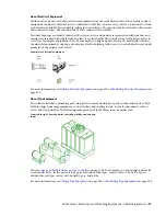
Electrical drawings are usually shown in 2D, where devices and panels are represented with symbols, and
wiring is represented with single lines. In plan view, electrical MvParts display the actual part geometry to
scale. You can display equipment in 3D. For example, you might want to show a 3D model that includes
the electrical equipment, conduits, and cable trays for the building. In this case, you can display the real-world
geometry of the objects in a 3D view.
Examples of electrical equipment
on page 419 or
Modifying Electrical Equipment
on
page 444.
About Pipe Equipment
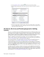
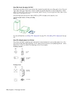
The software includes a plumbing part catalog that contains hundreds of parts in thousands of sizes. Pipe
MvParts range from large equipment, such as chillers and cooling towers, to small components, such as
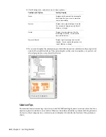
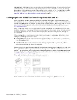
valves and fire sprinklers. The following example shows Pipe MvParts in an isometric view.
From left to right: Firetube boiler, centrifugal chiller, and cooling
tower
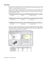
change an MvPart from one type to another
on page 324. For example, you can change a ball valve
to a butterfly valve. In the part catalogs, parts are divided into types, such as valves. The Valves type is
divided into subtypes such as ball, butterfly, gate, and globe.
on page 322.
Mechanical, Electrical, and Plumbing Equipment in Building Systems | 77
Summary of Contents for 235B1-05A761-1301 - AutoCAD MEP 2010
Page 1: ...AutoCAD MEP 2010 User s Guide March 2009 ...
Page 22: ...4 ...
Page 86: ...68 ...
Page 146: ...128 ...
Page 180: ...162 ...
Page 242: ...Modifying the elevation of a duct 224 Chapter 6 Drawing HVAC Systems ...
Page 264: ...246 ...
Page 480: ...462 ...
Page 534: ...516 ...
Page 616: ...598 ...
Page 658: ...640 ...
Page 788: ...770 ...
Page 802: ...784 ...
Page 820: ...802 ...
Page 878: ...860 ...


