


Description
Object
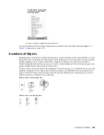
A block symbol used to specify real-world equipment or parts, such as fittings or valves, that
works in conjunction with schematic lines. It connects to schematic lines by breaking into
Schematic Symbol
the line or attaching to the end of the line when added. The properties of a schematic symbol
are system and ID.
A style-based part generated based on predefined properties to which other parts can be
connected. It has multiple annotation styles for crossing segments and connections, and
Wire
multiple graphic representation styles for different types of wire. It cleans up when additional
wire segments, accessories, panels, and devices are connected.
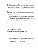
Matching Object Properties
Use the match properties feature when you want to match the style and object display properties between
AutoCAD MEP objects of the same type. For MEP objects of different types you can use the command to
match basic AutoCAD properties. Likewise, you can match basic AutoCAD properties between an AutoCAD
entity and an AEC object.
When you match properties between some style-based MEP objects, both the style properties and the display
properties of the selected source object are applied to one or more selected destination objects. For
non-style-based objects and most style-based objects, only display properties are matched. In either case,
the display properties are applied to all display representations of the destination object.
Object Types for Which Only Display Properties Are
Matched
Object Types for Which Both Style and Display
Properties Are Matched
Cable Tray
Fabrication
Cable Tray Fitting
Hangers
Conduit
Label Curve
Conduit Fitting
Plumbing Lines
Device
Schematic
Duct
Wire
Duct Custom Fitting
Duct Fitting
Duct Flex
Multi-View Part
Panel
Pipe
Pipe Fitting
Pipe Custom Fitting
106 | Chapter 4 Drawing Essentials
Summary of Contents for 235B1-05A761-1301 - AutoCAD MEP 2010
Page 1: ...AutoCAD MEP 2010 User s Guide March 2009 ...
Page 22: ...4 ...
Page 86: ...68 ...
Page 146: ...128 ...
Page 180: ...162 ...
Page 242: ...Modifying the elevation of a duct 224 Chapter 6 Drawing HVAC Systems ...
Page 264: ...246 ...
Page 480: ...462 ...
Page 534: ...516 ...
Page 616: ...598 ...
Page 658: ...640 ...
Page 788: ...770 ...
Page 802: ...784 ...
Page 820: ...802 ...
Page 878: ...860 ...