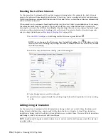

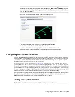
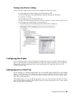


gbXML command exports only those zones that have spaces assigned. Zones without spaces assigned to
them will not be exported.
1
Select a zone.
2
Click the Add (Plus) grip.
NOTE
Alternatively, click Click Zone tab
➤
Modify panel
➤
Attach
.
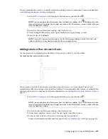
3
Select the spaces or zones to attach to the zone.
You can attach spaces or zones in reference drawings to a zone in the current drawing.
4
Continue attaching spaces to zones using the previous steps.
IMPORTANT
Zones in reference drawings cannot be exported to gbXML unless they are attached
to a zone in the current drawing. However, even when a zone in a reference drawing is attached to
a zone in the current drawing, any zone will not be exported if the spaces attached to it are attached
to other zones that have already been added to the export map.
TIP
You can use the Space/Zone Manager to review the zone hierarchy, and to review space
information such as surface and opening type. For more information, see Opening the Space/Zone
Manager and Editing Space Surface Properties.
Exporting Zones for Load Analysis
After you have configured spaces with property set values and have attached spaces to zones, you can export
the engineering and building information in gbXML format.
1
Open the drawing that contains the zone data you want to analyze.
NOTE
You can analyze a complete building by attaching zones and spaces in xref drawings to zones
in a current drawing. The adjacent spaces and space surface types are automatically detected for all
spaces at export.
2
Click
➤
Export
➤
gbXML.
If necessary, scroll down to display additional export options.
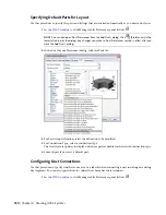
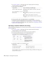
3
In the Export to gbXML dialog, specify the export settings:
■
File name: Specify a file name and location.
■
Select Objects: The dialog automatically detects all zones in the current drawing. Zones in
reference drawings cannot be exported unless they are attached to a zone in the current
drawing. If the dialog does not detect all zones, click Select Objects and select the desired
zones.
■
Building Type: Specify a building type and postal ZIP code that may be used by the external
analysis program.
■
Progress: Click Start to run the export.
190 | Chapter 6 Drawing HVAC Systems
Summary of Contents for 235B1-05A761-1301 - AutoCAD MEP 2010
Page 1: ...AutoCAD MEP 2010 User s Guide March 2009 ...
Page 22: ...4 ...
Page 86: ...68 ...
Page 146: ...128 ...
Page 180: ...162 ...
Page 242: ...Modifying the elevation of a duct 224 Chapter 6 Drawing HVAC Systems ...
Page 264: ...246 ...
Page 480: ...462 ...
Page 534: ...516 ...
Page 616: ...598 ...
Page 658: ...640 ...
Page 788: ...770 ...
Page 802: ...784 ...
Page 820: ...802 ...
Page 878: ...860 ...