


3
Select an object.
4
Click Home tab
➤
Build panel
➤
Tools drop-down
➤
Properties
.
5
Under Object Display Properties, configure settings for the current configuration as follows:
a
Select Yes for Above level override, and then specify a value for Above range.
b
Select Yes for Cut height override, and then specify a value for Cut height.
c
Select Yes for Below level override, and then specify a value for Below range.
BEST PRACTICE
Some objects spanning multiple cut planes might include a Rise/Drop symbol on
an elevation-based display component that is turned off, causing the object to be hidden. In those
cases, you can override the cut plane for that particular object so that it appears in the drawing area.
To apply cut plane overrides in the Display Manager
1
Select
in the Options dialog.
2
Click Manage tab
➤
Style & Display panel
➤
Display Manager
.
3
Expand the Configurations folder.
4
Select a display configuration from the list.
5
Click the Cut Plane tab in the right pane.
6
Apply the desired override for the display configurations that use this display representation.
then...
If you want to...
enter a value for Display Above Range.
define the visible range above the cut plane
enter a value for Cut Height.
define the cut plane height
enter a value for Display Below Range.
define the visible range below the cut plane
The values you enter for the Above and Below ranges are not relative to the cut height. They
are absolute height values calculated from the WCS origin. Therefore, the value that you enter
for Display Above Range must be greater than the value that you enter for Cut Height. Invalid
values will produce incorrect results.
NOTE
The Calculate button on the Cut Plane tab is only available if you selected a project using
Project Navigator and the current drawing is multi-story. It opens a Cut Plane dialog that you use to
set the cut plane height for objects at a specific level. For more information, see Levels in the AutoCAD
Architecture Help.
Display of Crossing Objects in 2-Line Plan Views
You can change the appearance of hidden lines, layers, line types, or color for crossing or overlapping objects
at different elevations in 2-line plan views.
Configuring the Display of a Gap Between Crossing Objects
You can configure a gap to display between crossing objects or disable hidden lines for MvParts. These
settings are applied to all objects in the drawing.
Display of Crossing Objects in 2-Line Plan Views | 151
Summary of Contents for 235B1-05A761-1301 - AutoCAD MEP 2010
Page 1: ...AutoCAD MEP 2010 User s Guide March 2009 ...
Page 22: ...4 ...
Page 86: ...68 ...
Page 146: ...128 ...
Page 180: ...162 ...
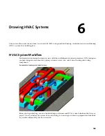
Page 242: ...Modifying the elevation of a duct 224 Chapter 6 Drawing HVAC Systems ...
Page 264: ...246 ...
Page 480: ...462 ...
Page 534: ...516 ...
Page 616: ...598 ...
Page 658: ...640 ...
Page 788: ...770 ...
Page 802: ...784 ...
Page 820: ...802 ...
Page 878: ...860 ...