


2
, open the style by doing one of the following:
■
Click Manage tab
➤
Style & Display panel
➤
Style Manager drop-down
➤
Schematic Line
Styles
. In the left pane of the Style Manager, select the style.
■
In the drawing, select a schematic line that uses the style, and click Schematic Line
tab
➤
General panel
➤
Edit System Style drop-down
➤
Edit Schematic Line Style
.
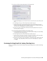
3
Click the Designations tab.
4
Define the designations:
then…
If you want to…
click
, click the Designation field, enter an ID, and press ENTER.
add a designation
click the corresponding Designation field, edit the ID, and press ENTER.
edit a designation
select a designation, and click
.
delete a designation
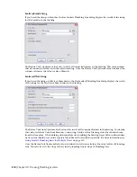
Specifying Annotation for Schematic Line Styles
When you draw a schematic line, you can select a style for the line on the Properties palette. The style
determines the annotation properties for the line, such as the symbols used to represent start points,
endpoints, and connections.
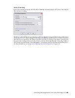
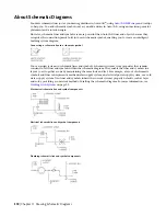
The style of a schematic line also determines how crossing lines are displayed. You can display crossing lines
as is, or with an overlap or a break of a specific width.
If you select the overlap style or break style, you must also specify a corresponding priority value. In a
drawing, if 2 crossing lines have the same priority value in their corresponding styles, the line with the lower
Configuring Styles for Schematic Lines | 523
Summary of Contents for 235B1-05A761-1301 - AutoCAD MEP 2010
Page 1: ...AutoCAD MEP 2010 User s Guide March 2009 ...
Page 22: ...4 ...
Page 86: ...68 ...
Page 146: ...128 ...
Page 180: ...162 ...
Page 242: ...Modifying the elevation of a duct 224 Chapter 6 Drawing HVAC Systems ...
Page 264: ...246 ...
Page 480: ...462 ...
Page 534: ...516 ...
Page 616: ...598 ...
Page 658: ...640 ...
Page 788: ...770 ...
Page 802: ...784 ...
Page 820: ...802 ...
Page 878: ...860 ...