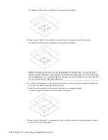

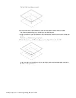
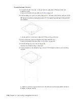

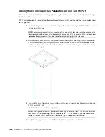

A diameter dimension (D1) is added to the model for the diameter of the knockout, a connector
is added to Connections, and D1 size parameter is added to Size Parameters.
IMPORTANT
The position of the first connector placed in the model defines the axis orientation of
the part upon insertion. For example, if you place the first connector on a part with a perpendicular
vector into the part, the direction of the vector defines the positive x-axis orientation when inserted
into a drawing.
4
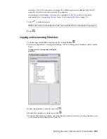
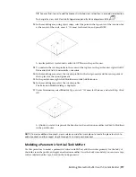
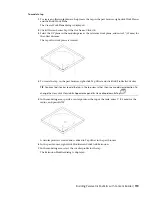
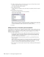
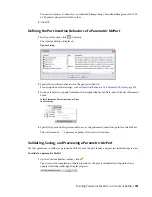
To define the domain and type of connection for the connector, in the part browser, expand
Connections, right-click Connector 1, and click Edit.
The Connector Properties dialog is displayed.
5
Select Conduit for Domain from the list.
Connector domains are dependent on the specified shape of the modifier to which the connector
is attached.
6
Select Glued for Type from the list.
Connector types are dependent on the connector domain.
NOTE
Connectors are assigned an undefined type by default. An undefined connection type creates
a valid connection between all types of connectors when inserted in a drawing.
7
Click OK.
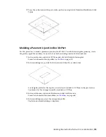
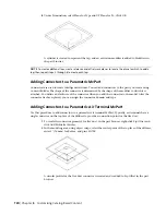
Adding Connectors to a Parametric Vertical Tank MvPart
Use this procedure to add connectors to a parametric vertical tank MvPart. Typically, tanks have multiple
connectors, an inlet and an outlet. This procedure provides steps to add a connector for the inlet of a vertical
tank. You can repeat this procedure, making the necessary location adjustments to add other connectors.
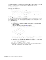
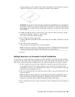
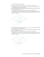
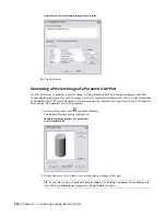
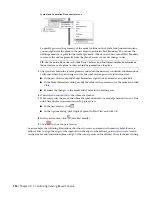
1
To add a connector, in the part browser, right-click Connections and click Add Connection.
You are prompted to select the connector location. As you move the cursor around in the
modeling area, it snaps to 4 possible locations for a connector—the top and bottom of the tank
body and the top and bottom of the tap.
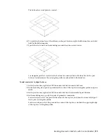
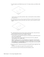
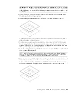
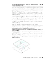
2
Select the center point of the top of the tap and press
ENTER
to accept the default value for the
connector number.
NOTE
The default connector numbers are in ascending numeric order, according to the order in
which the connectors are added to the model. For example, the first connector is 1, the second
connector is 2, and so on. You can model connections for MvParts in any order.
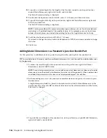
3
Pick a location above and to the right of the model to place the dimension for the diameter of
the tap.
Building Parametric MvParts with Content Builder | 723
Summary of Contents for 235B1-05A761-1301 - AutoCAD MEP 2010
Page 1: ...AutoCAD MEP 2010 User s Guide March 2009 ...
Page 22: ...4 ...
Page 86: ...68 ...
Page 146: ...128 ...
Page 180: ...162 ...
Page 242: ...Modifying the elevation of a duct 224 Chapter 6 Drawing HVAC Systems ...
Page 264: ...246 ...
Page 480: ...462 ...
Page 534: ...516 ...
Page 616: ...598 ...
Page 658: ...640 ...
Page 788: ...770 ...
Page 802: ...784 ...
Page 820: ...802 ...
Page 878: ...860 ...


