


8
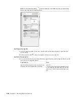
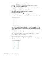
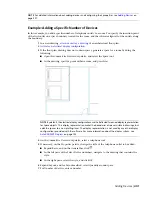
In the drawing, move the cursor to the location for the first device. This must be a point on the
space boundary.
NOTE
If the software does not detect a space boundary, you can still insert the devices and have the
software align them automatically, but you must manually specify the location for each device one
at a time.
9
Examine the preview of the telephone outlets, and if necessary, move the cursor to a different
location on the boundary.
NOTE
On the Properties palette, you can view the value for Distance between. This read-only property
is updated when the preview is displayed.
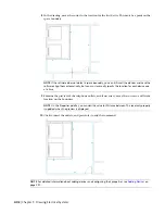
10
Click to insert the outlets, and press
Enter
to end the command.
NOTE
For detailed information about adding devices and configuring their properties, see
on
page 391.
402 | Chapter 9 Drawing Electrical Systems
Summary of Contents for 235B1-05A761-1301 - AutoCAD MEP 2010
Page 1: ...AutoCAD MEP 2010 User s Guide March 2009 ...
Page 22: ...4 ...
Page 86: ...68 ...
Page 146: ...128 ...
Page 180: ...162 ...
Page 242: ...Modifying the elevation of a duct 224 Chapter 6 Drawing HVAC Systems ...
Page 264: ...246 ...
Page 480: ...462 ...
Page 534: ...516 ...
Page 616: ...598 ...
Page 658: ...640 ...
Page 788: ...770 ...
Page 802: ...784 ...
Page 820: ...802 ...
Page 878: ...860 ...


