


3
Select the polylines, lines, or arcs that represent the centerline of the custom fitting, and press
ENTER
.
4
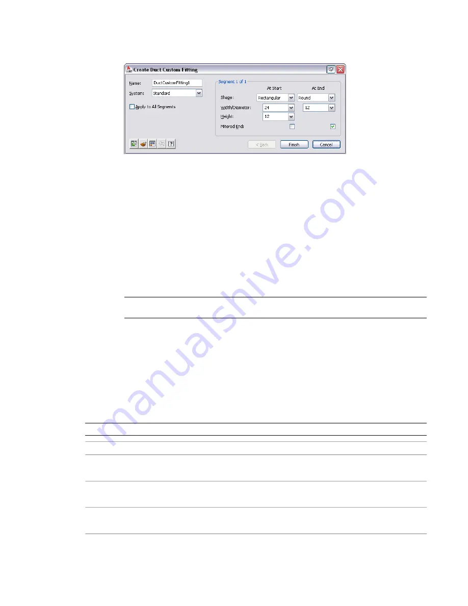
In the Create Custom Fitting dialog, enter a name, and then select a system.
5
Specify the shape and size for the start and end of each segment, and then select Mitered End
if an end is mitered.
Use the Object Viewer to view the segment you are specifying properties for. As you step through
the Create Custom Fitting dialog, the Object Viewer highlights the current segment.
6
If the properties assigned to the current segment are the same for all segments, select Apply to
All Segments.
7
If the properties of the next segment are different from those of the current segment, click Next.
The Next button is not available if you select Apply to All Segments.
8
Click Finish, and enter y (yes) to erase the original centerline geometry or n (no) to keep the
original geometry in the drawing.
9
Press
ENTER
.
NOTE
If any size or shape properties of the segments are incomplete, the custom fitting cannot be
created and the Missing Size or Shape Information error message is displayed.
Using the Part Size Not Found Dialog
Sometimes, when adding or modifying a part, the size that you define does not fit the criteria defined in
the part catalogs. In these cases, you are prompted with the Part Size Not Found dialog. Use this dialog to
select an alternate size definition for the part.
The top portion of the dialog indicates the size criteria that is incompatible with the part you defined. For
example, you specify a height for a takeoff. If the values that you define in the part filter are not matched
within the catalog, you can create a custom size.
NOTE
Not all parts that are included in the program support custom sizing.
then…
If you want to…
select a part size from the list, and click Use selected part size from
catalog.
use a part from the catalog
click Create custom sized part.
create a new part to maintain the values that you
defined
click Ignore and continue.
use the values that you defined for the part, and
allow an invalid connection to be made
Adding Duct | 217
Summary of Contents for 235B1-05A761-1301 - AutoCAD MEP 2010
Page 1: ...AutoCAD MEP 2010 User s Guide March 2009 ...
Page 22: ...4 ...
Page 86: ...68 ...
Page 146: ...128 ...
Page 180: ...162 ...
Page 242: ...Modifying the elevation of a duct 224 Chapter 6 Drawing HVAC Systems ...
Page 264: ...246 ...
Page 480: ...462 ...
Page 534: ...516 ...
Page 616: ...598 ...
Page 658: ...640 ...
Page 788: ...770 ...
Page 802: ...784 ...
Page 820: ...802 ...
Page 878: ...860 ...


