


Example
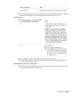
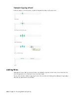
Wire Segment Type
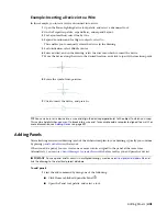
Spline.
Use this type to draw wires with curves that pass through
or near a set of specified points.
To add wires
1
In the
, start the add command by doing
one
of the following:
■
Click Home tab
➤
Build panel
➤
Wire
.
■
Select the + grip on a device
■
Open the Wire tool palette, and select a tool.
If necessary, scroll to display the tool. Because tools contain preconfigured properties for the
objects they create, you might not need to specify some of the wire properties referenced in
this procedure.
■
Enter
wireadd
.
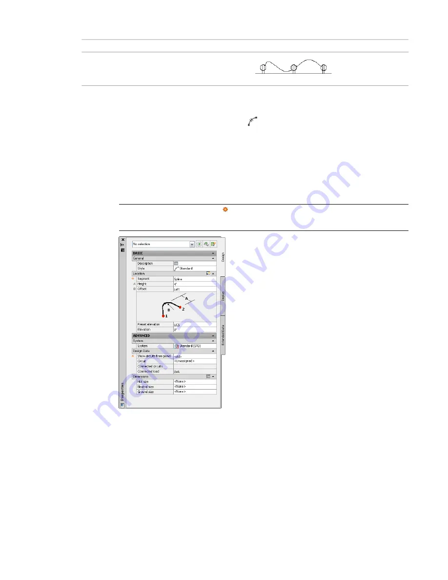
NOTE
On the Properties palette,
indicates a property is available only when you are adding
wires, not when you are modifying them.
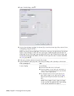
Specify general properties (optional when using the + grip)
2
On the Properties palette, if necessary, specify or change the wire to add by selecting a wire style:
■
Expand Basic, and expand General.
■
For Style, select a wire style.
You can select from the wire styles in the current drawing.
If you want to calculate wire sizes using the instant sizing tool, do not select the Standard style
provided with the software. By default, that style does not specify a wire material, which is
required to calculate the sizes.
414 | Chapter 9 Drawing Electrical Systems
Summary of Contents for 235B1-05A761-1301 - AutoCAD MEP 2010
Page 1: ...AutoCAD MEP 2010 User s Guide March 2009 ...
Page 22: ...4 ...
Page 86: ...68 ...
Page 146: ...128 ...
Page 180: ...162 ...
Page 242: ...Modifying the elevation of a duct 224 Chapter 6 Drawing HVAC Systems ...
Page 264: ...246 ...
Page 480: ...462 ...
Page 534: ...516 ...
Page 616: ...598 ...
Page 658: ...640 ...
Page 788: ...770 ...
Page 802: ...784 ...
Page 820: ...802 ...
Page 878: ...860 ...


