


For more information on solution tips, see
on page 579.
6
If necessary, reconnect disconnected components in the run by adding connecting segments,
changing the elevation of segments, or
components. You can recreate
valid connections using
.
Modifying the Location Coordinates of a Plumbing Line or Fitting
The preferred method for moving plumbing lines and fittings is to
. However, you can also
modify the location of a plumbing line using the Properties palette.
To change the location coordinates
1
on page 492 the plumbing line in your drawing that you want to modify.
2
Click Home tab
➤
Build panel
➤
Tools drop-down
➤
Properties
.
3
On the Design tab of the Properties palette, under Placement
➤
Elevation, click
Additional
Information.
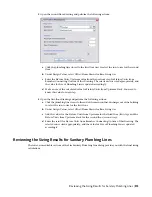
4
In the Location dialog, specify the placement or orientation changes.
then…
If you want to…
under Insertion Point, specify the new X, Y, and Z coordinates, and
click OK.
specify a new location
under Normal, specify 1 for the normal axis and 0 for the other 2
axes, and click OK.
change the normal axis, and reorient
the part along the new normal
IMPORTANT
Using this method to modify the location coordinates of a plumbing line will cause
the plumbing line to disconnect from any plumbing runs to which it is currently connected.
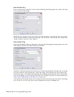
Modifying the Nominal Size of a Plumbing Line Segment
1
on page 492 the plumbing line segment in your drawing.
2
Click Home tab
➤
Build panel
➤
Tools drop-down
➤
Properties
.
3
On the Design tab of the Properties palette, under Dimensions, specify a different nominal size.
4
Specify a new size for Nominal Size.
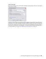
TIP
You can lock Nominal size. When locked, the nominal size list is inactive and the associated
diameter cannot be modified. You can, however, still modify the length or elevation of a plumbing
object. To turn off a size, unlock this setting on the Properties palette.
NOTE
Alternatively, you can select a plumbing line, click Plumbing Line tab
➤
Modify panel
➤
Modify
Plumbing Line
, and change the setting for Nominal Size or lock the setting.
The plumbing line style determines the appearance and function of the line, including size. As
a result, the
dictates the nominal sizes that are available for selection
on the Properties palette.
NOTE
Since plumbing lines are two-dimensional (2D) only, the size of a plumbing line is for calculation
purposes only. Changing the size of a plumbing line does not automatically insert the necessary
fitting.
500 | Chapter 10 Drawing Plumbing Systems
Summary of Contents for 235B1-05A761-1301 - AutoCAD MEP 2010
Page 1: ...AutoCAD MEP 2010 User s Guide March 2009 ...
Page 22: ...4 ...
Page 86: ...68 ...
Page 146: ...128 ...
Page 180: ...162 ...
Page 242: ...Modifying the elevation of a duct 224 Chapter 6 Drawing HVAC Systems ...
Page 264: ...246 ...
Page 480: ...462 ...
Page 534: ...516 ...
Page 616: ...598 ...
Page 658: ...640 ...
Page 788: ...770 ...
Page 802: ...784 ...
Page 820: ...802 ...
Page 878: ...860 ...